TABLE OF CONTENTS
- Silhouette Studio Drawing Tablet Compatibility
- Create Custom Cut Settings in Silhouette Studio
- Track Enhancing
- Silhouette Studio Cut Line Options
- How to Cut By Line/Fill/Layer
- How to Trace Imported Images
- Custom Color Values in Silhouette Studio
- Drawing in Silhouette Studio
- Print and Cut Feature (Using Registration Marks)
- Converting Regular Cut Design into Print & Cut Design
- Print Bleed Feature
- Stencil Letters and Designs
- Convert to Path Feature
- Offset Feature
- Text Features
- Pasting Text into Silhouette Studio
- PixScan™ Feature Overview
- How to Flip or Mirror Designs
- Trace and Detach Feature
- How to Create Frames for Sketch Designs
- How to Ungroup and Group Designs
- Drawing Your Own Designs in Silhouette Studio
- How to Customize Material Size Options
- Using PNG Files in Silhouette Studio
- Sizing Designs to Exact Measurements
- Using Patterns in Silhouette Studio
- How to Convert Lines to Dashed Lines
- Batch Import Multiple Files into Silhouette Studio
- To import multiple files into your library as a batch job is to do the following:
- How to Open GST Files in Silhouette Studio
Silhouette Studio Drawing Tablet Compatibility
Silhouette Studio can be controlled with the use of a drawing tablet and stylus (such as a Wacom tablet).
A drawing tablet can be used by plugging the tablet to your computer, and then opening the Silhouette Studio program. From there, you can use the tablet in a similar fashion you would otherwise use a mouse tool. If you select the "Draw Freehand" tool, this will allow you to draw using the tablet device directly.
Silhouette cannot support or guarantee connectivity/compatibility of Silhouette Studio with any specific drawing tablet.
Silhouette Studio Spell Check Feature
Silhouette Studio includes a spell check feature when creating text using the Text tool.
When the software encounters an unknown word and assumes a misspelling, a blue line will appear under the word in question.

How to Use Spell Check
To use the 'Spelling' feature:
- Right-click on the incorrect text to select one of the following:
- Select the corrected text from options listed on the top of the right-click menu (if present)
- Select 'Add [word] to Dictionary' if it is correct (to eliminate the blue line indicator for this word going forward)
- Select 'Spelling' from the right-click menu if you don't see the correct spelling and the word is incorrect
NOTE: The 'Spelling' panel may include additional suggestions
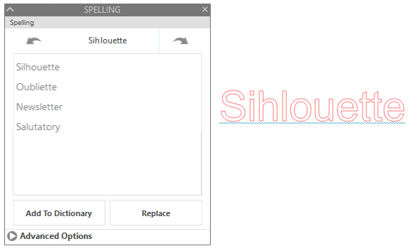
- If needed, select one of the desired actions in the 'Spelling' panel
- Click the Forward or Back arrows at the top of the panel to see more suggestions (if available)
- Select the correct word and click on 'Replace' to update the text
- Select 'Add [word] to Dictionary' if it is correct (to eliminate the blue line indicator for this word going forward)
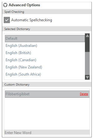
- Update 'Advanced' options, as desired
- Enable/disable 'Automatic Spellchecking'
- Select an alternate dictionary or dialect for your preferred language
NOTE: Not all software program languages are availble - Add new words to be recognized going forward
Create Custom Cut Settings in Silhouette Studio
You can create or edit custom cut settings in Silhouette Studio as follows.
Add New Material
- Open Silhouette Studio
- Go to the SEND tab
- Click on the material drop-down list
- Click on Add New Material Type
- A new material window will open at the bottom of the panel
- Name your material type
- Select the material family type from the drop-down list on the right hand side of the screen
NOTE: This helps the software determine how to handle the material for select actions - Define your Cut action settings
- If desired, click on the Plus icon to add additional actions and define these as well
- Once all information is entered as desired, click on the SAVE button
Your new material will appear at the bottom of the Material Settings list.
Edit Existing Material
- Open Silhouette Studio
- Go to the SEND tab
- Click on the material drop-down list
- Select your desired material type
- Make any desired changes to the settings
- Once all information is entered as desired, click on the SAVE button
The updated settings will now be present going forward whenever selecting this material type.
Track Enhancing
Track enhancing is a feature that moves your material back and forth through the Silhouette machine prior to the actual cutting process.
As material thickness increases, the rollers (dependent upon the material type and surface) might not grip as firmly on the material's surface during operation. In such cases, you may enable the Track Enhancing option. The action of feeding the material through the Silhouette several times prior to operation creates a "track" on the material's edges for the Silhouette to gain a better grip upon during the actual job. The feature attempts to ensure proper alignment of secondary passes performed and may resolve potential cutting mis-alignment concerns.
This option is only needed when cutting thicker materials where the material appears to be otherwise slipping during the cutting action, or when there is mis-alignment when cutting multiple passes.
Silhouette Studio Cut Line Options
With any design inside the defined cutting area, you have the option to enable or disable the cut lines. The design must be selected in order to adjust these settings.
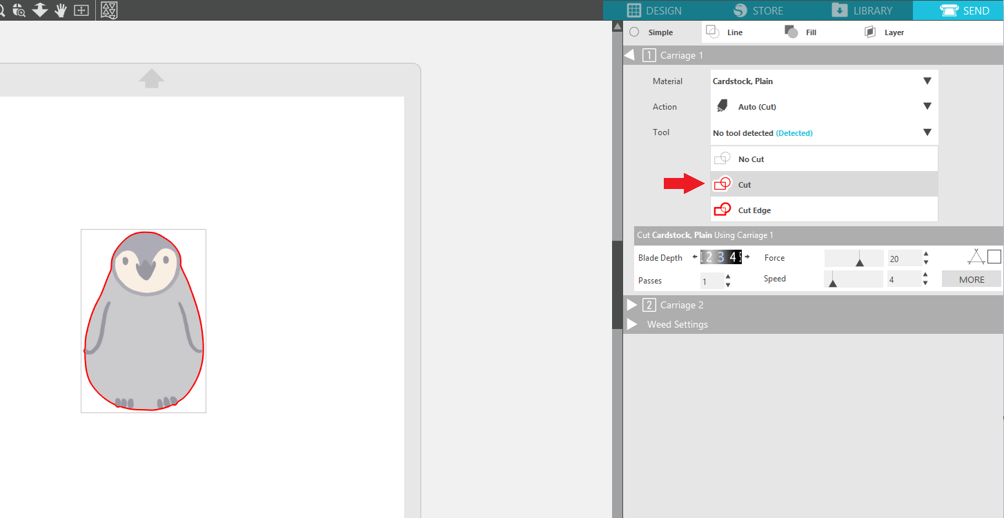
There are three line processing options found in the Silhouette Studio SEND Panel for enabling/disabling your cut lines:
- Cut
- Cut Edge
- No Cut

Cut all lines of the selected design, indicated by a medium weight line.

Cut only the outer line(s) of the selected design, indicated by a thick weight line.

This option will disable the cut lines of the selected design so they are not cut by the Silhouette machine, indicated by a very light weight line.
Adjusting Line Options
Unable to Select Lines
If the design is not allowing you to select certain lines, it's possible you may either need to select the design and Ungroup it in order to work with individual parts, or you may need to select the design and Release the Compound Path so that specific lines can be separated and selected individually.
You can do this as follows:
- Go to the Design tab to view your workspace
- Select the design
- Right-click
- Select Ungroup and/or Release Compound Path
How to Cut By Line/Fill/Layer
Silhouette Studio provides several methods for processing your designs as they are sent to the cutting machine.
Though the software will default to cut according to Simple setting options, you can alternately select to cut by line color, cut by fill type, or cut by layers.
Cut By Line Color or Fill Color
To cut by line color or fill color:
- Open Silhouette Studio
- Create your design containing multiple line or fill colors
- Go to the SEND panel
- Click on the Line tab or Fill tab at the top of the panel
- Adjust your settings for each line or fill color as desired
- If you would like to adjust any actual line colors or fill colors for your designs, go to the DESIGN panel and adjust your designs as desired
Cut by Layers
If you have the Designer Edition or above, you will additionally have access to the Layers feature.
Once layers are assigned through the Layers feature, you can cut by layers as follows:
- Open Silhouette Studio
- Create your design containing multiple layers
- Go to the SEND panel
- Click on the Layers tab at the top of the panel
- Adjust your settings for each layer as desired
- If you would like to assign parts of your design to different layers, go to the DESIGN panel and select the Layers button
Pausing Between Groups
Sometimes pausing between groups may be necessary. For example, you may be using sketch pens and want to switch pen colors between each group.
If you would like add a Pause between defined groups (according to line color, fill type, or layer), you can do the following:
- Click on the chosen material setting
- Right-click to select "Add Pause"
The Silhouette machine will then pause after the selected material type has completed its defined action, but before moving on to the next group.
How to Trace Imported Images
You can use your own images created in other programs with Silhouette Studio using the Trace feature. The Trace panel can be found in the right-hand side toolbar, or by going to the Panels menu and selecting Trace.

Compatible Files for Tracing
All editions of Silhouette Studio can import external images in a basic raster image format, including:
- PNG
- JPG
- BMP
- GIF
- TIF
DISCLAIMER: Not all images are designed in such a way that they can be traced well for cutting purposes. Silhouette cannot support or guarantee results for files not offered by our company.
How to Trace
To Trace in Silhouette Studio:
- Open Silhouette Studio
- Go to File > Open
- Locate and open the image file
NOTE: If on a PC, "All Files" may need to be selected from the "file type" selection in the "Open" window in order to locate your files - Click on the Trace icon

- Click on the Select 'Trace Area' option

- Draw a box around the image that is desired to be traced
NOTE: The trace filter will show a yellow area covering the image. This yellow area is a preview of where your cut lines would be created.
- Adjust the tracing filters to your liking.
Filter options are as follows:
- High Pass Filter
Trace lines are created beginning from the outside of your image. Trace lines move toward the inside of the image as the filter setting is adjusted upward. This is a good option if you are trying to create a basic cutting frame from a more detailed image.
- Threshold
Determines how broadly the trace filter is applied beginning with the darkest colors for low settings and light colors for higher settings.
- Scale
low-qualityControls the smoothness of edges around the image. This setting is typically only required when using low-quality or pixilated images.
- Once the trace area has been drawn and the desired filter settings are in place, select the desired tracing method under 'Apply Trace Method'.
Trace options are as follows:
- Trace
Traces all outer and inner lines. This is generally preferable if you are attempting to create a regular cut image with multiple parts and specific details to be cut.
- Trace Outer Edge
Creates a cut line only around the outer edges of your image. This is generally preferable if you are attempting to create a Print & Cut image.
- Trace and Detach
Detaches a portion of the print image from its original background. This can be helpful if you need to remove the white background of an imported print image, or just want to work with one smaller part of the imported image.
Scanning Images Directly into Silhouette Studio
Silhouette Studio provides a direct scan access feature. This allows the software to access a connected scanner and import images directly into the Silhouette Studio software program.
Scaningg Images into Silhouette Studio
To scan images into Silhouette Studio:
- Power on your scanner
- Place your image on the scanner bed
- Open Silhouette Studio
- Go to the File > Scan option
- Select your scanner from the list of available devices
NOTE: If you don't see your scanner listed, make sure it is connected to your computer and powered on - Press the 'Start Scan' button
Your image will be scanned directly into the design workspace.
IMPORTANT: Scanned images will not have any cut line data. You can use the Trace feature to create cut lines, if desired.
Custom Color Values in Silhouette Studio
Silhouette software programs use RGB, HEX, and HSL color value control options.
CMYK color value options are not currently supported.
NOTE: If desired, you can find a website to convert your CMYK colors to RGB values
Apply Custom Color Values
Update color values to customize lines or fill colors as follows:
- Open Silhouette Studio
- Select the Fill panel (to fill designs with color), or the Line Style panel (to change line colors)

- Scroll down to the bottom of the panel to find the 'Custom Color' section
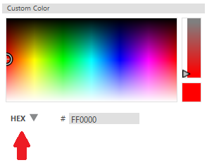
- Set the color value to the desired format (RGB, HEX, or HSL), and enter the desired value
Add Custom Colors to Palette
You can create a custom palette with specific colors as follows:
- Open Silhouette Studio
- Go to the Line Style or Fill Panel
- Click on "New Palette Name" and enter a name

- Draw a line
- Adjust the color as instructed in the "Apply Custom Color Values"
- Click on the '+' symbol next to the palette name
This will add the color to your palette
Drawing in Silhouette Studio
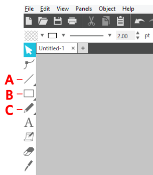
Silhouette Studio offers a variety of drawing tools to create your own custom designs.
These tools are found on the left-hand toolbar:

Specific sub-tool options can be found by hovering over these icons.
How to Draw
To use drawing tools:
- Select your drawing tool
- Place your cursor in the Design area
- Hold down the left-click button on your mouse and drag the cursor
- Once finished drawing, release the left-click button
- Click back on the Select tool to continue to move, resize, or otherwise adjust your designs
 NOTE: If you do not click on the Select tool, you will continue to draw additional shapes until you have selected a different tool
Changing Default Behavior
If you prefer your cursor to revert immediately to the basic Select tool after using a drawing tool:
- Open Silhouette Studio
- Go to File > Preferences > Tools
- Adjust any desired behavior under the 'Action After Tool Use' section
Print and Cut Feature (Using Registration Marks)
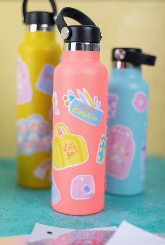
The Print & Cut feature allows you to send a project from the Silhouette software program to your printer, and then load the printed page into your Silhouette cutting machine to cut the defined cut lines, usually defined around the printed design's contour.
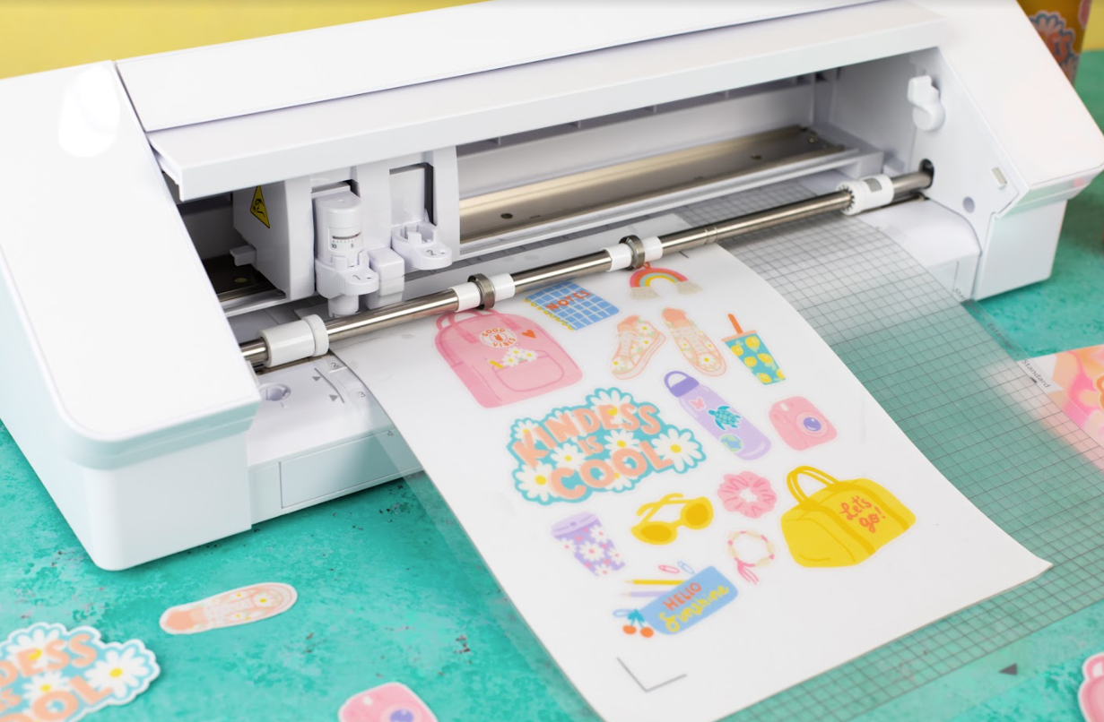
The resulting cut-out project provides a custom-cut printed design.
This feature is included in all editions of Silhouette Studio. All Silhouette machine models have an optic sensor to read Registration Marks and accommodate the Print & Cut feature.
Getting Started with Print & Cut
Registration Marks
The Print & Cut process requires the use of Registration Marks. Registration Marks are a series of marks that are printed near the corners of your page.

The Silhouette cutting machine's optic sensor will find the registration marks on your printed material and know accordingly where to cut your defined cut lines, usually around the contour of the printed design.
Turning on Registration Marks
IMPORTANT: Registration Marks are only for Print & Cut jobs where you are printing a project and then feeding the printed page into the Silhouette machine to be cut. If you are not performing a Print & Cut job, you will need to turn off Registration Marks.
To enable your Registration Marks for Print & Cut jobs:
- Open Silhouette Studio
- Go to the Page Setup panel (on the upper right-hand toolbar)

- Click on the 'Registration Mark' icon
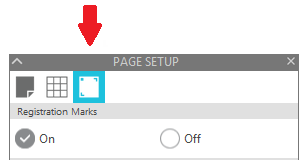
- Select the 'On' option
Print & Cut Designs
Some designs offered in the Silhouette Design Store are ready-made Print & Cut designs. You can identify these by the 'P' appearing on the thumbnail's bottom left-hand corner.

You can also create your own Print & Cut projects with imported print images with which you can trace to create cut lines.
Setting Up Print & Cut Design
Once you have your Print & Cut design (print image with associated cut lines), make sure that the design is placed properly within the available printing and cutting area.
IMPORTANT: Make sure the design does not overlap the registration marks, hash mark areas, cut border, or print border.

Printing the Job
Once your design is placed and sized to your liking, press the 'Print' icon to send the job to your printer.

IMPORTANT: Do not make any changes to the document in the Silhouette Studio software after printing. Otherwise, the printed version and software version will no longer match and the job will not be cut properly If any changes are made to the Design area, you will need to re-print your job.
Loading the Job into the Silhouette Cutting Machine
After you have your printed page, load the printed page according to your 'Cutting Mat' selection in the software.
IMPORTANT: If you have set the job to use a cutting mat, then you must use the corresponding selected cutting mat. If you selected 'None' for the cutting mat, then you will need to load the material directly into your Silhouette cutting machine. If you adjust the 'Cutting Mat' setting in the software, you will need to re-print your job after making adjustments.

Cutting the Job
When you're ready to send the job to be cut:
- Go to the Send panel in Silhouette Studio
- Select your material settings
- Click on the 'Send' button when ready
The Silhouette cutting machine will then locate the registration marks and then proceed to cut your job.
Compatible Material Sizes
If you have a Portrait model, then the maximum Print & Cut material size is 8.5 x 11 inches.
If you have a Cameo model, then the maximum Print & Cut material size is 12 x 12 inches.
NOTE: While larger Cameo models (Cameo Plus and Cameo Pro) can technically allow larger material sizes, we recommend a maximum material size of 12 x 12 inches, and to use a cutting mat in order to ensure proper Print & Cut registration alignment.
Converting Regular Cut Design into Print & Cut Design
Some designs offered from the Silhouette Design Store are ready-made Print & Cut designs. You can identify these by the 'P' appearing on the thumbnail's bottom left-hand corner.
Images with no icon on the thumbnail will indicate a Regular Cut designs.
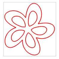
Regular Cut designs will have cut lines around each design piece whereas Print & Cut designs will typically have a cut line only around the outer contour of the overall design.
Converting Regular Designs for Print & Cut
You can convert Regular Cut designs into Print & Cut files by doing the following:
- Open the Regular Cut design into your workspace
- Right-click and select Ungroup
NOTE: With some designs, you may need to select Release Compound Path in order to work with individual design parts - Select a design component you want to color
- Open the Fill panel
- Select a desired fill color or pattern
Converting Regular Designs into Paper Piecings
Some Regular Cut designs have individual pieces designed to be cut from different colored materials and then assembled after cutting (see Miss Kate Cuttables designs). These are often called "paper-piecing" designs.
For a more advanced project, you can turn a paper-piecing, regular cut file into a Print & Cut file as follows:
- Open the Regular Cut design.
- If you see red cut lines with no other filled color, you will need to add color.
NOTE: If the design is already filled with color, you may proceed to step 5 below. - To add color, perform the steps listed in the instructions above
- Repeat until all shapes are filled with your desired colors
- Click and drag the pieces to assemble the image in the software, as desired.
NOTE: You may need to right-click on select shapes to "Bring to Front" if they are not properly layered visually. - Once the design appears as desired, select all shapes together
- Right-click and select Group
- With the design selected, go to the SEND panel
- Select the Cut Edge option
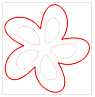
You should have a colored image with one active cut line around the outer edge only. Though they may still show in the software, all other red cut lines will not print out or be cut.
Print Bleed Feature
The Print Bleed feature provides an expanded print bleed for your Print & Cut jobs, ensuring that the contour cut performed around the printed edge appears to be better aligned.
This feature is included in all editions of Silhouette Studio.
How to Use Print Bleed
To use the Print Bleed feature:
- Open Silhouette Studio
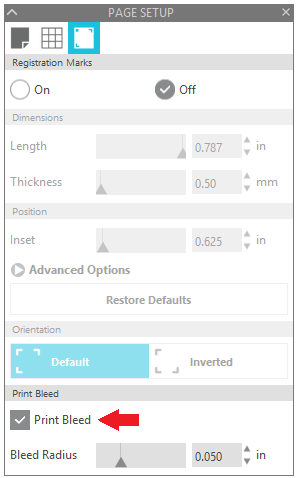
- Go to the Page Setup panel

- Go to the 'Registration Marks' tab
- Check the 'Print Bleed' option
NOTE: This action will extend the printed design. This allows your Silhouette machine to cut off the excess color on your Print & Cut leaving no white edges on your final cutout. You will not see a preview of the print bleed on your design page at this time. It will only show up after the document is printed
- Adjust the 'Bleed Radius setting, if desired. This will make the bleed radius more or less pronounced.
- Print your job
NOTE: The printout with print bleed enabled may look unexpected and a little awkward because of the extra color. Rest assured that the extra color will be cut off during the Print & Cut job.
- Send your job to your Silhouette cutting machine, as you normally would with a Print & Cut job.
The resulting cut should show the white border reduced or eliminated entirely around the cut-out image:

Image Background Types
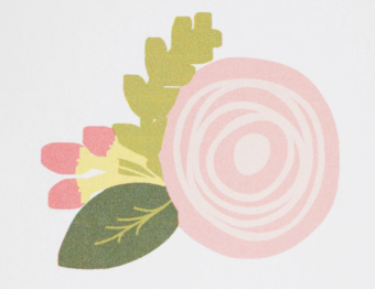
You will not see any Print Bleed effect if your design has a white background (example below).

The background around your design must be clear (example below) for this feature to work properly.

If your design has clear space between the colored portions and the cut line but the cut lines don’t hug the design (example below), your print bleed may not work the way you want it to.

If you intentionally want to have a white border around your designs (example below), then turn off Print Bleed, or make sure that the area that extends beyond your colored portion has a white fill color instead of clear.

Stencil Letters and Designs
Letters and designs intended for stencil projects typically require the inner parts of the designs (islands) to be connected by a space (bridge) to the outside of the design.
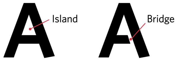
Letters and designs that have islands without bridges will create stencils that drop inner details.

Stencils from the Silhouette Design Store
The Silhouette Design Store offers many ready-made stencil fonts and designs.
You can find these offerings by searching for the term 'Stencil' and filtering for the desired digital content type (fonts, regular cut images, etc.)
Convert Regular Designs into Stencil Designs
Some letters and designs can be manually adjusted to be converted into a stencil.
To do so:
- Create your letter or design

- Draw a small shape (such as a rectangle) that connects the inside island to the outer boundary of the letter or design

- Select both objects together
- Open the 'Modify' panel

- Select the 'Subtract' option

- Select and move the letter or design to view the new stencil

You can alternately use the Knife and/or Eraser tool in 'Solid' mode to create bridges.
Convert to Path Feature
The 'Convert to Path' feature allows you to convert select shape types into an editable format where line points can be edited.
The two most common uses for this option are:
- Ability to adjust curves and points
- Ability to send a file to another person who does not have the same font installed on their computer
EXAMPLE: Person A has 'Specific' font installed on their computer. They create a Studio document with text saying "Thank You" in 'Specific' font. Person B does not have 'Specific' font installed on their computer. If Person A sends a saved copy of the created Studio file to Person B, the text style in the document would revert to 'Ariel' or another standard font that the software can find on Person B's computer.
However, using 'Convert to Path' on the text prior to sending the document will allow Person B to see an image of the font that looks like it is in 'Specific' font styling. However, the text would not be editable by Text tools anymore since it has been converted from text into a path.
This feature is available in all software editions.
Vector Line Shape Types
Silhouette Studio supports three classes of vector line shapes:
- Bezier-curve images (can have individual points or nodes edited)
- Text (editable as text)
- Pre-set adjustable shapes (special Studio tool shapes with built-in adjustment features)
Bezier-Curve Shapes
Shape tools in Silhouette Studio, such as Line, Rectangle, and Ellipse, are 'Bezier-curve' shapes. Designs from the Silhouette Design Store are also typically in Bezier-curve format. This means the shape can have individual node points edited.

This represents most designs used.
Text Shapes
Lettering using fonts installed on your computer can be created with the Text tool.
Once created, text can be adjusted into different font styles, easily edited to update the letters or words, and adjusted using various text tools.
When converting text to a path, the lettering will become just an image of the letters. This means that while the text object might look the same, it can no longer be changed to a different font style, edited, or updated by using the text tools. However, the curves and nodes can now be edited.

Pre-set Adjustable Shapes
Pre-set adjustable shapes, such as rounded rectangles and Flexishapes, can be created with various drawing tools in Silhouette Studio. These special shape types include dedicated adjustment control points allowing the shape to be manipulated and adjusted in a way other shapes cannot.

Once created, these shapes can continue to be adjusted using the provided control points.
When converting text to a path, the shape will become just an image of the shape. This means that while it looks the same, it can no longer be changed using the special control points. However, the curves and nodes can now be edited.
Converting Other Shapes to Bezier-Curves
In order to allow the editing of curves and nodes of Text shapes or pre-set adjustable shapes:
- Select the shape
- Right-click
- Select 'Convert to Path'
Offset Feature
This feature is included in the Basic Edition and above.
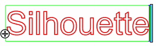
Silhouette Studio provides an Offset feature to create matting effects (sometimes referred to 'shadowing' or 'creating shadows'). This is where an additional offset line is created either outside or inside the design's original outer lines.
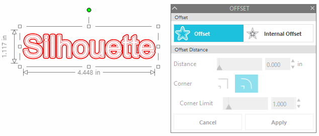
Creating Offsets
To create a matting effect for your image:
- Open the Offset panel (on the right-hand tool bar)

- Click on your design to select it
- Click on the 'Offset' or 'Internal Offset' option
'Offset' Example:

'Internal Offset' Example:

- Adjust the 'Offset Distance' options to your desired settings
Offset Distance: The greater the number, the farther away the traced shadow or mat will be from the original design
Corner vs. Round: The corner option will provide sharp edges while the round option will provide smooth edges
NOTE: You will not be able to adjust these settings after you hit 'Apply' in the next step. They can only be manipulated while being created.
- Once finished, click Apply
Offset Video
Text Features
Silhouette Studio offers a variety of text feature options and other software tools to manipulate your text appearance.
Font Style Preview
One of the most important decisions when using text is selecting the right font.
Though you can of course see the basic style represented by looking at the font list, you can also have the font list display a specific word to preview how it would specifically look in that font option.
To use this feature:
- Open the Text Style panel
- Click in the box labeled "Enter preview text here" (below the font list)
- Type a word you'd like to preview
The font list will be updated to show your word in each font style as you scroll through the list.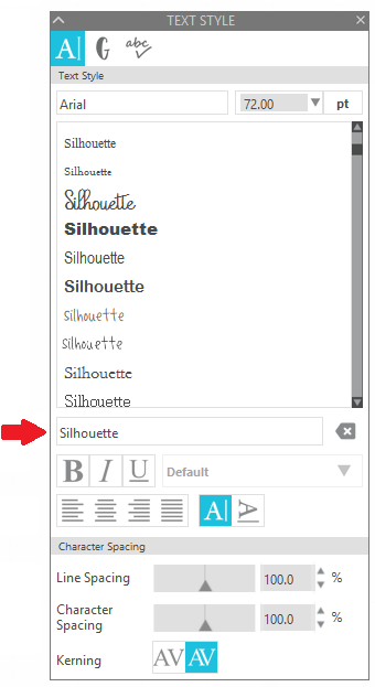
To turn this off and revert to the actual font names, press the 'delete' icon to the right of the preview text field.

Making Text Thicker
To thicken text letters, you can either:
- Use the Bold option in the Text Style panel
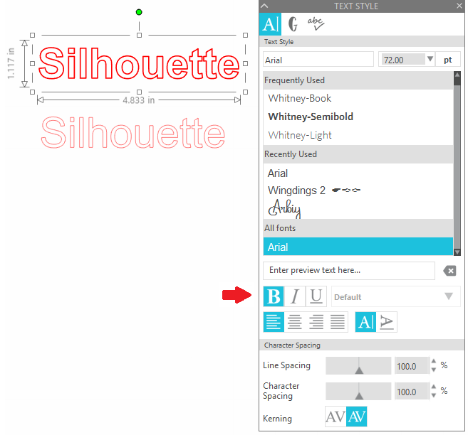
- Use the Offset feature
Curved Text / Text to Path
The 'Text to Path' feature allows you to place text along a curve to create an arced effect.

To create this effect:
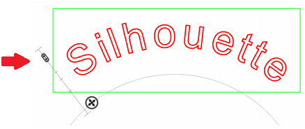
- Create a circle, arc, or other curved image
NOTE: In the example above, the Arc tool was used

- Create the desired text
- While in the Text Editing mode (where the text is surrounded by a green editing box), locate the small control point on the lower left-hand side of the text box
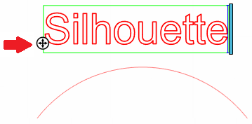
- Click and hold down on this control point
- Move your text control point onto the desired line
 NOTE: This feature can be used to drag text onto any line path, but works best when using an arced or circle pattern
- Use the vertical control point (to the left of your text) to set the text into position above, along, or below the line in order to acheive the desired look.
 NOTE: The line or object your text is placed on will automatically turn off any cutting or other action for that line or object.
Vertical Text
Text is defaulted to create horizontally (left to right), but can be adjusted to create vertical text.
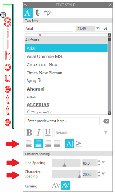
To create vertical text:
- Go to the Text cursor tool
- Create your text in the desired font style
- While still in the text edit mode (with the green box around the text), click on the black bar (to the right of the text) and drag it to the left (back towards the first letter of your text)
- If there are any lines showing two letters on the same line, place your cursor in front of the second letter on that line and press the Enter key on your keyboard to move it onto its own line
- In the Text Style settings, select the Center option, and adjust the Line Spacing and Character Spacing to your liking
Kerning
Kerning is the spacing between individual characters. Unlike the 'Character Spacing' option, which adjusts the amount of space between characters accross the entire selected word in equal increments, kerning adjusts each character individually in order to create the most visually pleasing spacing for that specific font style.
The Kerning feature in the Text Style options can be toggled on to control character kerning for fonts that have such available.
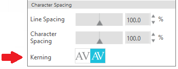
When Kerning is toggled on, the spacing between each letter is fine tuned according to the data provided by the font author. Pairs of letters which fit nicely together will be moved closer together.
For example:
- If a letter 'A' is followed by letter 'V', then kerning moves these letters closer because 'AV' fist together nicely.
- If letter 'A' is followed by letter 'M', these letters do not fit together particularly well, so kerning might not typically adjust these two letters.
NOTE: Kerning information is stored inside the font file; it is not computed by Silhouette Studio. Therefore, the specific adjustments applied by kerning depend completely upon the values defined by the font author.
Pasting Text into Silhouette Studio
This feature is included in the Basic Edition and above.
Text copied from other applications can be pasted directly into the Silhouette Studio software.
Pasting Text
To paste text into Silhouette Studio:
- Open Silhouette Studio
- Open the other program or source from where the text will be copied
- Select the desired text
- With the text highlighted, hold down [Ctrl]+C on the keyboard, or right-click and select 'Copy' (this copies the text)
- Go back to Silhouette Studio
- Click in the design area
- Hold down [Ctrl]+V on the keyboard, or right-click and select 'Paste' (this pastes the text)
NOTE: You do not need to access any Text cursor or Text Edit panel tools for this action. Pasting is performed without selecting any specific software tools.
Your intended text should appear in your design area. The font style will default to the first font found in the program (usually 'Ariel') at a 72-point font size.
You can resize and adjust the text as desired.
Pasting Limitation
If the intended text does not show up after following the above steps, this indicates that too much text was selected. Silhouette Studio has a limitation on how much information can be pasted into the software.
If such is the case, you will need to copy and paste smaller strings of text in smaller sections, rather than a larger section of text all at once.
PixScan™ Feature Overview
This feature is included in All Editions of Silhouette Studio
PixScan™ technology is a feature of the Silhouette cutting system that provides the ability to capture an image using a scanner or digital camera (including smartphones and tablets) by taking a picture of the printed image on a special PixScan cutting mat.
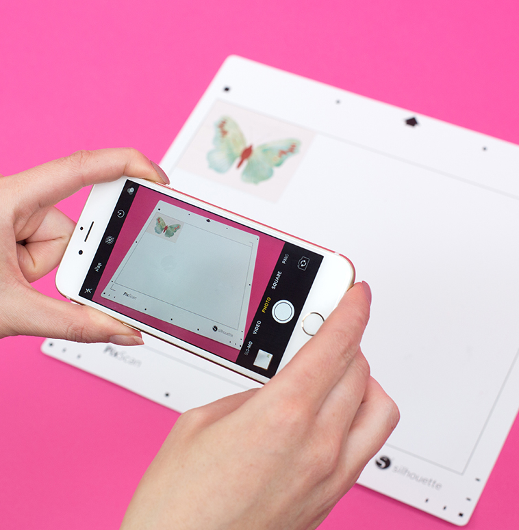
The captured image can then be imported into Silhouette Studio and used to create cut lines around the image -- in its exact size and location on the cutting mat.

This allows you to cut around any pre-printed or hand-drawn designs.

The PixScan feature requires the use of a PixScan Cutting Mat with a compatible Silhouette cutting machine model (according to the PixScan mat type in use).
PixScan Use Cases
PixScan is ideal for:
- Turning hand-drawn sketches and lettering into cut jobs
- Digitizing printed patterns
- Adding custom-cut borders and frames to professionally printed invitations
- Replicating a pattern at its original size
- Saving material and time using the Nesting feature to place images to be cut within specially shapped materials (Designer Edition and above only)
- Incorporating printed images or patterns into your custom craft projects
- Turning photos and other printed clippings into cut or sketch files
- Cutting precisely around already existing printed or stamped images
NOTE: PixScan is only intended to help digitize your own original artwork and photos
PixScan Compatibility
PixScan mats are compatible with all Portrait, Cameo, and Curio cutting machine models.
Note: The Curio 2 is not compatible with the PixScan mats
PixScan requires Silhouette Studio version 3.1 or higher.
How to Use PixScan
To use the PixScan feature:
- Place your printed image onto the PixScan mat.
IMPORTANT: The material must fit entirely inside the rectangular workspace border on the mat - Capture an image of the entire mat using either a digital camera, such as a smartphone, or a scanner.
- Camera: Set the PixScan mat on a flat surface. Take a digital photo of the entire mat with the printed image on the mat. The photograph must be taken straight-on rather than at an angle. You will need to then save the photo to your computer where you are using Silhouette Studio.
- Scanner: Scan the entire PixScan mat with the printed image on the mat. If necessary, you can perform two scans, one for each end of the mat if you have a smaller scanner that cannot fit the entire scan in one pass. If performing two scans, the software will stitch the scans together for you automatically.
IMPORTANT: Once you have captured your image, do not adjust any object placement on the PixScan mat. If any adjustments are made, you will need to re-capture a new image
- Click on the 'PixScan' icon (on the right-hand toolbar)

- Photo: Select the Camera icon in the PixScan panel, and click on 'Import PixScan Image from File'
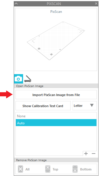
- Scanner: Click on the Scanner icon, then Import PixScan Image from Scanner

Once imported, your cutting mat will display as your PixScan cutting mat in the software
- Add cut lines to your imported image as desired using the Trace feature
- Load the PixScan mat into your machine
- Proceed to cut
PixScan Video
How to Flip or Mirror Designs
This feature is included in All Editions of Silhouette Studio
Select material types, such as Heat Transfer Vinyl, may require you to cut out your design backwards so that it is properly oriented onto your project surface once applied. This is especially important when using text so that letters are facing the correct direction on the final project.
NOTE: This is only required for select material types. Check product instructions to verify if this action is necessary.
Mirroring Designs
To mirror a design:
- Create and select your design
- Right-click and select 'Flip Horizontally'

This will ensure your material is cut in a mirrored orientation:
The result, once applied to your project surface, will be that your design is displayed properly:
Trace and Detach Feature
This feature is included in All Editions of Silhouette Studio
When tracing imported images, the 'Trace' or 'Trace Outer Edge' options are most often used in order to create cut lines. However, you may not want to trace and use all parts of an imported image.
The 'Trace and Detach' option is a special option that removes print images from their original background.
 This allows you to work with individual portions of an image rather than having to print and use the entire original design.
How to Trace and Detach
To use the Trace and Detach feature:
- Open Silhouette Studio
- Open your print image

- Go to the Trace panel

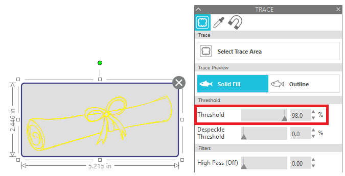
- Click 'Select Trace Area'
- Draw the trace area around the desired part of the image. As needed, resize the trace area so that your desired part of the image is fully enclosed in the trace area.
NOTE: Don't worry if your trace area overlaps onto unintended portions of the image

- If your design is does not have the yellow trace preview around all parts of the intended image you're wanting to detach, increase the 'Threshold' value until the design is fully traced to the outer-most edges.

- Click on 'Trace and Detach'
NOTE: If your image is very large or overly complex, this action can take a few minutes - Click and move the detached image off to the side of the original image
- Delete the original image background
This action to Trace and Detach a portion of an imported image will create a cut line around the outside of the newly detached image.
How to Create Frames for Sketch Designs
This feature is included in All Editions of Silhouette Studio
Sketch designs are sometimes intended to be drawn directly onto the project surface.

However, you can alternately sketch the design onto its own material, and then create an accompanying background frame for your sketch design. This can give your project added dimension.

Sketch Design Frames
To create a frame for a sketch design:
- Open your sketch design
- Open the Trace panel
- Click on 'Select Trace Area' and draw around the contour of the sketch design
- Increase the 'Threshold' until the outer lines of the design are yellow
- Select 'Trace Outer Edge'
- Click in the center of your sketch design and move it away from the newly traced outer line

- Click on the newly traced outer line to select it
- Open the Offset panel (on the right-hand toolbar)

- Click on the 'Offset' option
- Adjust the 'Distance' to your liking
- Click 'Apply'
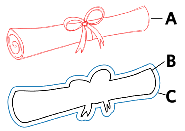
You should now have:
A) the original sketch design
B) an outer cut line (used to cut out the sketch design after it has been drawn)
C) an offset frame (used to cut out a different material as a background)
NOTE: For ease of reference, you may want to set each design part as a different line color
Once you have all of the design components ready:
- Select 'A' (the original sketch) and 'C' (the outer cut line) together
- Click on the 'Center' icon (top dynamic toolbar)
 NOTE: This action will align 'A' (sketch design) with 'C' (outer cut line)
- Send the sketch design lines to your Silhouette machine to be drawn with a pen
IMPORTANT: Do not touch or unload your material once the sketch job is complete - Send the outer cut line to your Silhouette machine to be cut out with a blade
- Unload your job and remove the cut-out sketched design
- Load a new material color into the Silhouette cutting machine for the offset frame
- Send the offset frame to your Silhouette machine to be cut out with a blade
- Unload your job and remove the cut-out frame
- Assemble the cut-out sketch design onto the offset frame

How to Ungroup and Group Designs
This feature is included in All Editions of Silhouette Studio
Some digital content is offered as a collection of various images or related parts to assemble.

The actual file with cut lines may display the parts of the design separately, but have them all grouped together in the same file.
In these instances, you do not have to cut out the entire job with all design parts from the same sheet of material. You can work with only select portions of the design to be cut individually on specific material colors by using the 'Ungroup' feature.
NOTE: The following only pertains to cut-line content. Click here instead if you're working with Print & Cut designs.
Ungrouping
To ungroup designs:
- Select your design once it has been sized as desired
- Right-click on your design and select 'Ungroup'
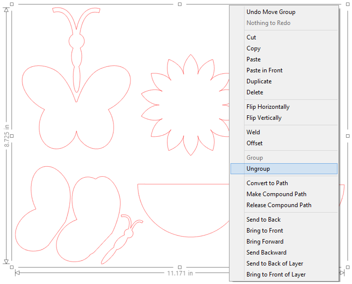
- Click to the side of the selected design in order to unselect it
- Click on any individual design part to work with it
NOTE: If the 'Ungroup' action does not allow you to work with a smaller design portion, you may need to use the 'Release Compound Path' feature instead.
Grouping
If you'd like to group designs together in order to move and manipulate design parts together:
- Select two or more design parts that are not currently together
NOTE: Make sure that the relative positioning of the selected design parts to each other is to your liking - Right-click and select 'Group'
Drawing Your Own Designs in Silhouette Studio
Silhouette Studio enables you to draw your own ready-to-cut art from within the software using an assortment of drawing tools.
Drawing
Tools for drawing are found on the left-hand toolbar. They include three major categories:
- Line Tools
- Drawing Tools
- Freehand Tools
Line Tools
Line tools can be accessed by hovering your mouse over the Line Tools icon

Line tools include the following:
Line Tool
 The Line tool is a simple single line. Click to drop the starting point, drag your mouse to the desired end location and then click again to drop the endpoint.

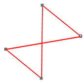
Polygon Tool

The Polygon tool allows to you create a series of connected straight lines. Click to drop the starting point, drag your mouse to the next desired line point and click to drop a new point. Once finished, you can stop drawing additional points by double-clicking your mouse, or by connecting the endpoint to the start point thus creating a closed shape.
After the polygon is created, you can double-click to enter 'Point Edit' mode and adjust any points.
Curved Shape

The Curved Shape tool works in the same way as the Polygon tool, but the lines are curved instead of straight.

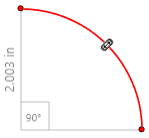
Arc

The Arc tool allows you to create an arc. Click and drag the mouse to a secondary point. This action creates the size of the arc. You will then click again to start the angle of the arc. Once you have the arc to your liking, click again to complete the arc.
TIPS:
- After the line is created, you can double-click to enter 'Point Edit' mode and adjust any points or resize your drawing.
- Use the Shift key to force straight-line tools into 45-degree angles.
- Double-click on drawn lines to enter Point Edit mode. This allows you to adjust any drawing after it is completed.
Drawing Tools
Drawing tools can be accessed by hovering your mouse over the Drawing Tools icon

Drawing tools include the following:
Rectangle Tool
 The Rectangle tool is a simple four-sided rectangle tool. Click to drop the starting point, drag your mouse to create the desired size and then click again to set the shape.

Rounded Rectangle Tool

The Rounded Rectangle tool is a simple four-sided rectangle tool with rounded corners. Click to drop the starting point, drag your mouse to create the desired size and then click again to set the shape.

Ellipse

The Ellipse (Circle) tool creates a round shape. Click to drop the starting point, drag your mouse to create the desired size and then click again to set the shape.

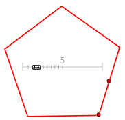
Polygon Shape

The Polygon Shape tool allows you to create a polygon shape with multiple straight-line sides. Click and drag the mouse to a secondary point. This action creates the size of the polygon. Click again to set the size. You can then click on the control point in the center to change the number of sides for your polygon shape.
TIPS:
- After the shape is created, you can double-click to enter 'Point Edit' mode and adjust any points or resize your drawing.
- The Shift key will force the rectangle or rounded rectangle into a square and will force the ellipse into a perfect circle.
- The Alt key will make the initial click-point the center of your drawn object.
- Double-click on drawn lines to enter Point Edit mode. This allows you to adjust any drawing after it is completed.
Freehand Tools
Freehand drawing tools can be accessed by hovering your mouse over the Freehand Tools icon

Freehand tools include the following:
Freehand
 Use the Freehand tool to draw a freehand object. Click and hold down your mouse button to draw a continuous free-form line. Release your mouse button to stop when you are finished drawing.

Smooth Freehand

Use the Smooth Freehand tool to draw a freehand object with smoother lines. Click and hold down your mouse button to draw a continuous free-form line. Release your mouse button to stop when you are finished drawing.
The Freehand tool is exact while the Smooth Freehand tool will automatically smooth the line as it is being drawn.

When using the Smooth Freehand tool, you can adjust the smoothing effect to be more or less precise with your drawing.

How to Customize Material Size Options
Aside from the standard common material sizes available in the Silhouette Studio program, you can define your own material sizes.
CAUTION: Creating a custom material size may create a workspace that cannot be accommodated by your cutting machine model.
Defining Custom Sizes
To define a custom material size:
- Open Silhouette Studio
- Go to the Page Setup panel (on the right-hand toolbar)

- Set the 'Media Size' option to 'Custom'

- Adjust the Width and Height settings according to your material size
NOTE: Unfortunately, you are not able to save custom sizes for later use at this time.
Using PNG Files in Silhouette Studio
PNG files are raster images that can handle graphics with transparent or semi-transparent backgrounds.
Opening PNG Files (Importing)
All editions of the Silhouette Studio software can open PNG files, including the free Basic Edition.
To open a PNG file:
- Open Silhouette Studio
- Click on the Open icon
- Navigate to the file
- Select the file and click "OK"
Some PNG files may have transparent backgrounds. The default behavior of Silhouette Studio will open these images with auto-traced cut lines around the edges of the transparent image.
This auto-trace feature for PNG files can be toggled on/off as follows:
- Open Silhouette Studio
- Go to Edit > Preferences > Import
- Check or uncheck the "Autotrace" box under the PNG section
- Click Apply
- Click OK
If the auto-trace feature is off or the image does not have a transparent background, then the image will not immediately have cut lines. You can use the Trace feature to create cut lines as needed.
Sizing Designs to Exact Measurements
To adjust designs to exact measurements in Silhouette Studio:
- Select your design
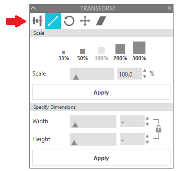
- Open the Transform panel (on the right-hand toolbar)

- Go to the Scale tab
- Make sure the lock aspect ratio icon is in the 'locked' position
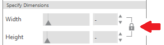
- Specify your exact desired 'Height' OR 'Width' for your design, depending on which measurement is more critical
NOTE: You can only select 'Height' or 'Width'. If you want to specify both measurements, you will need to click on the aspect ratio icon to toggle it off. Results when adjusting both measurements may cause undesired visual results. - Click Apply
Using Patterns in Silhouette Studio
Patterns are available as a fill type for designs created in Silhouette Studio. This allows you to create unique Print & Cut projects.
Using Patterns
To use Patterns:
- Open the Fill panel

- Click on the Pattern fill tab

- Select your design
- Click on the desired pattern
Additional Pattern Options
Once you have a pattern fill selected for your design, you can continue to adjust the filled effect with the following options.
- Transparency - Scales the transparency of the fill from 0% (opaque) to 100% (transparent)
- Aspect Ratio - Either maintains the aspect ratio of the filled pattern (default) or stretches the aspect ratio
- Mirror Pattern - Either maintains the original pattern (default) or mirrors the pattern
- Scale - Scales the pattern size to be larger or smaller within the filled object
- Pan Pattern - Provides control to move the pattern around inside the filled object
- Rotate Pattern - Controls the angle of rotation of the pattern design
Adding Patterns
You can obtain additional ready-to-use fill patterns from the Silhouette Design Store.
If you have purchased a pattern from the Silhouette Design Store but cannot find it:
- Open Silhouette Studio
- Go to the Library
- Go to the 'Patterns' folder
- Locate your desired pattern
Your purchased patterns will also appear in the Fill panel.
If you are unable to locate your pattern by browsing, you can look up the design ID in the software Library.
Design ID in Silhouette Design Store
You can also add your own patterns as instructed in the video below:
How to Convert Lines to Dashed Lines
To convert solid lines to dashed lines:
- Open Silhouette Studio
- Create your design
- Open to the Line Style panel

- Click on the line you'd like to adjust
- Select the "Style" drop-down option and select the desired line style

Batch Import Multiple Files into Silhouette Studio
To import multiple files into your library as a batch job is to do the following:
- Open Silhouette Studio
- Go to the Library
- Locate the files on your computer in their saved location
- Select the files you want to import
- Drag and drop the files from your computer into any folder in your library
NOTE: This process is only available for compatible file types, based on your Silhouette Studio edition
IMPORTANT: When saving content into your software library, always maintain another backup copy of your own files outside of the software program. While Silhouette does sync selected content between devices, we cannot help to recover custom content that has been removed or lost from your library due to a computer crash or other uncontrollable event.
How to Open GST Files in Silhouette Studio
GST is the file type used previous to Studio.3. Some designs on the Silhouette Design store are still in this format. Below are steps to open this file in Silhouette Studio
Windows
- Direct Download the file from the order by clicking the download button under the file in the order
- Then click save to save to your computer
- Right click the downloaded file and click Extract/Unzip
- Right click on the extracted GST file and click 'Open With'
- If you do not see Silhouette Studio click 'Choose another app' and find Silhouette Studio
- You can then save the file as Studio.3 or export to any file type allowed by your version
Mac
- Direct Download the file from the order by clicking the download button under the file in the order
- Double click the zipped folder and right click the GST
- click 'Choose Application' then 'Choose All Applications' and find Silhouette Studio
- It should then open directly or via file open and you can then save as Studio.3 or export as any file type allowed by your version
- Select the corrected text from options listed on the top of the right-click menu (if present)
- Select 'Add [word] to Dictionary' if it is correct (to eliminate the blue line indicator for this word going forward)
- Select 'Spelling' from the right-click menu if you don't see the correct spelling and the word is incorrect
NOTE: The 'Spelling' panel may include additional suggestions
- Click the Forward or Back arrows at the top of the panel to see more suggestions (if available)
- Select the correct word and click on 'Replace' to update the text
- Select 'Add [word] to Dictionary' if it is correct (to eliminate the blue line indicator for this word going forward)
- Enable/disable 'Automatic Spellchecking'
- Select an alternate dictionary or dialect for your preferred language
NOTE: Not all software program languages are availble - Add new words to be recognized going forward
You can create or edit custom cut settings in Silhouette Studio as follows.
Add New Material
- Open Silhouette Studio
- Go to the SEND tab
- Click on the material drop-down list
- Click on Add New Material Type
- A new material window will open at the bottom of the panel
- Name your material type
- Select the material family type from the drop-down list on the right hand side of the screen
NOTE: This helps the software determine how to handle the material for select actions - Define your Cut action settings
- If desired, click on the Plus icon to add additional actions and define these as well
- Once all information is entered as desired, click on the SAVE button
Your new material will appear at the bottom of the Material Settings list.
Edit Existing Material
- Open Silhouette Studio
- Go to the SEND tab
- Click on the material drop-down list
- Select your desired material type
- Make any desired changes to the settings
- Once all information is entered as desired, click on the SAVE button
The updated settings will now be present going forward whenever selecting this material type.
Track Enhancing
Track enhancing is a feature that moves your material back and forth through the Silhouette machine prior to the actual cutting process.
As material thickness increases, the rollers (dependent upon the material type and surface) might not grip as firmly on the material's surface during operation. In such cases, you may enable the Track Enhancing option. The action of feeding the material through the Silhouette several times prior to operation creates a "track" on the material's edges for the Silhouette to gain a better grip upon during the actual job. The feature attempts to ensure proper alignment of secondary passes performed and may resolve potential cutting mis-alignment concerns.
This option is only needed when cutting thicker materials where the material appears to be otherwise slipping during the cutting action, or when there is mis-alignment when cutting multiple passes.
Silhouette Studio Cut Line Options
With any design inside the defined cutting area, you have the option to enable or disable the cut lines. The design must be selected in order to adjust these settings.
There are three line processing options found in the Silhouette Studio SEND Panel for enabling/disabling your cut lines:
- Cut
- Cut Edge
- No Cut
Cut all lines of the selected design, indicated by a medium weight line.
Cut only the outer line(s) of the selected design, indicated by a thick weight line.
This option will disable the cut lines of the selected design so they are not cut by the Silhouette machine, indicated by a very light weight line.
Adjusting Line Options
Unable to Select Lines
If the design is not allowing you to select certain lines, it's possible you may either need to select the design and Ungroup it in order to work with individual parts, or you may need to select the design and Release the Compound Path so that specific lines can be separated and selected individually.
You can do this as follows:
- Go to the Design tab to view your workspace
- Select the design
- Right-click
- Select Ungroup and/or Release Compound Path
How to Cut By Line/Fill/Layer
Silhouette Studio provides several methods for processing your designs as they are sent to the cutting machine.
Though the software will default to cut according to Simple setting options, you can alternately select to cut by line color, cut by fill type, or cut by layers.
Cut By Line Color or Fill Color
To cut by line color or fill color:
- Open Silhouette Studio
- Create your design containing multiple line or fill colors
- Go to the SEND panel
- Click on the Line tab or Fill tab at the top of the panel
- Adjust your settings for each line or fill color as desired
- If you would like to adjust any actual line colors or fill colors for your designs, go to the DESIGN panel and adjust your designs as desired
Cut by Layers
If you have the Designer Edition or above, you will additionally have access to the Layers feature.
Once layers are assigned through the Layers feature, you can cut by layers as follows:
- Open Silhouette Studio
- Create your design containing multiple layers
- Go to the SEND panel
- Click on the Layers tab at the top of the panel
- Adjust your settings for each layer as desired
- If you would like to assign parts of your design to different layers, go to the DESIGN panel and select the Layers button
Pausing Between Groups
Sometimes pausing between groups may be necessary. For example, you may be using sketch pens and want to switch pen colors between each group.
If you would like add a Pause between defined groups (according to line color, fill type, or layer), you can do the following:
- Click on the chosen material setting
- Right-click to select "Add Pause"
The Silhouette machine will then pause after the selected material type has completed its defined action, but before moving on to the next group.
How to Trace Imported Images
You can use your own images created in other programs with Silhouette Studio using the Trace feature. The Trace panel can be found in the right-hand side toolbar, or by going to the Panels menu and selecting Trace.
Compatible Files for Tracing
All editions of Silhouette Studio can import external images in a basic raster image format, including:
- PNG
- JPG
- BMP
- GIF
- TIF
DISCLAIMER: Not all images are designed in such a way that they can be traced well for cutting purposes. Silhouette cannot support or guarantee results for files not offered by our company.
How to Trace
To Trace in Silhouette Studio:
- Open Silhouette Studio
- Go to File > Open
- Locate and open the image file
NOTE: If on a PC, "All Files" may need to be selected from the "file type" selection in the "Open" window in order to locate your files - Click on the Trace icon
- Click on the Select 'Trace Area' option
- Draw a box around the image that is desired to be traced
NOTE: The trace filter will show a yellow area covering the image. This yellow area is a preview of where your cut lines would be created. - Adjust the tracing filters to your liking.
Filter options are as follows:- High Pass Filter
Trace lines are created beginning from the outside of your image. Trace lines move toward the inside of the image as the filter setting is adjusted upward. This is a good option if you are trying to create a basic cutting frame from a more detailed image. - Threshold
Determines how broadly the trace filter is applied beginning with the darkest colors for low settings and light colors for higher settings. - Scale
low-qualityControls the smoothness of edges around the image. This setting is typically only required when using low-quality or pixilated images.
- High Pass Filter
- Once the trace area has been drawn and the desired filter settings are in place, select the desired tracing method under 'Apply Trace Method'.
Trace options are as follows:- Trace
Traces all outer and inner lines. This is generally preferable if you are attempting to create a regular cut image with multiple parts and specific details to be cut. - Trace Outer Edge
Creates a cut line only around the outer edges of your image. This is generally preferable if you are attempting to create a Print & Cut image. - Trace and Detach
Detaches a portion of the print image from its original background. This can be helpful if you need to remove the white background of an imported print image, or just want to work with one smaller part of the imported image.
- Trace
Scanning Images Directly into Silhouette Studio
Silhouette Studio provides a direct scan access feature. This allows the software to access a connected scanner and import images directly into the Silhouette Studio software program.
Scaningg Images into Silhouette Studio
To scan images into Silhouette Studio:
- Power on your scanner
- Place your image on the scanner bed
- Open Silhouette Studio
- Go to the File > Scan option
- Select your scanner from the list of available devices
NOTE: If you don't see your scanner listed, make sure it is connected to your computer and powered on - Press the 'Start Scan' button
Your image will be scanned directly into the design workspace.
IMPORTANT: Scanned images will not have any cut line data. You can use the Trace feature to create cut lines, if desired.
Custom Color Values in Silhouette Studio
Silhouette software programs use RGB, HEX, and HSL color value control options.
CMYK color value options are not currently supported.
NOTE: If desired, you can find a website to convert your CMYK colors to RGB values
Apply Custom Color Values
Update color values to customize lines or fill colors as follows:
- Open Silhouette Studio
- Select the Fill panel (to fill designs with color), or the Line Style panel (to change line colors)
- Scroll down to the bottom of the panel to find the 'Custom Color' section
- Set the color value to the desired format (RGB, HEX, or HSL), and enter the desired value
Add Custom Colors to Palette
You can create a custom palette with specific colors as follows:
- Open Silhouette Studio
- Go to the Line Style or Fill Panel
- Click on "New Palette Name" and enter a name
- Draw a line
- Adjust the color as instructed in the "Apply Custom Color Values"
- Click on the '+' symbol next to the palette name
This will add the color to your palette
Drawing in Silhouette Studio
Silhouette Studio offers a variety of drawing tools to create your own custom designs.
These tools are found on the left-hand toolbar:
Specific sub-tool options can be found by hovering over these icons.
How to Draw
To use drawing tools:
- Select your drawing tool
- Place your cursor in the Design area
- Hold down the left-click button on your mouse and drag the cursor
- Once finished drawing, release the left-click button
- Click back on the Select tool to continue to move, resize, or otherwise adjust your designs
NOTE: If you do not click on the Select tool, you will continue to draw additional shapes until you have selected a different tool
Changing Default Behavior
If you prefer your cursor to revert immediately to the basic Select tool after using a drawing tool:
- Open Silhouette Studio
- Go to File > Preferences > Tools
- Adjust any desired behavior under the 'Action After Tool Use' section
Print and Cut Feature (Using Registration Marks)
The Print & Cut feature allows you to send a project from the Silhouette software program to your printer, and then load the printed page into your Silhouette cutting machine to cut the defined cut lines, usually defined around the printed design's contour.
The resulting cut-out project provides a custom-cut printed design.
This feature is included in all editions of Silhouette Studio. All Silhouette machine models have an optic sensor to read Registration Marks and accommodate the Print & Cut feature.
Getting Started with Print & Cut
Registration Marks
The Print & Cut process requires the use of Registration Marks. Registration Marks are a series of marks that are printed near the corners of your page.
The Silhouette cutting machine's optic sensor will find the registration marks on your printed material and know accordingly where to cut your defined cut lines, usually around the contour of the printed design.
Turning on Registration Marks
IMPORTANT: Registration Marks are only for Print & Cut jobs where you are printing a project and then feeding the printed page into the Silhouette machine to be cut. If you are not performing a Print & Cut job, you will need to turn off Registration Marks.
To enable your Registration Marks for Print & Cut jobs:
- Open Silhouette Studio
- Go to the Page Setup panel (on the upper right-hand toolbar)
- Click on the 'Registration Mark' icon
- Select the 'On' option
Print & Cut Designs
Some designs offered in the Silhouette Design Store are ready-made Print & Cut designs. You can identify these by the 'P' appearing on the thumbnail's bottom left-hand corner.
You can also create your own Print & Cut projects with imported print images with which you can trace to create cut lines.
Setting Up Print & Cut Design
Once you have your Print & Cut design (print image with associated cut lines), make sure that the design is placed properly within the available printing and cutting area.
IMPORTANT: Make sure the design does not overlap the registration marks, hash mark areas, cut border, or print border.
Printing the Job
Once your design is placed and sized to your liking, press the 'Print' icon to send the job to your printer.
IMPORTANT: Do not make any changes to the document in the Silhouette Studio software after printing. Otherwise, the printed version and software version will no longer match and the job will not be cut properly If any changes are made to the Design area, you will need to re-print your job.
Loading the Job into the Silhouette Cutting Machine
After you have your printed page, load the printed page according to your 'Cutting Mat' selection in the software.
IMPORTANT: If you have set the job to use a cutting mat, then you must use the corresponding selected cutting mat. If you selected 'None' for the cutting mat, then you will need to load the material directly into your Silhouette cutting machine. If you adjust the 'Cutting Mat' setting in the software, you will need to re-print your job after making adjustments.
Cutting the Job
When you're ready to send the job to be cut:
- Go to the Send panel in Silhouette Studio
- Select your material settings
- Click on the 'Send' button when ready
The Silhouette cutting machine will then locate the registration marks and then proceed to cut your job.
Compatible Material Sizes
If you have a Portrait model, then the maximum Print & Cut material size is 8.5 x 11 inches.
If you have a Cameo model, then the maximum Print & Cut material size is 12 x 12 inches.
NOTE: While larger Cameo models (Cameo Plus and Cameo Pro) can technically allow larger material sizes, we recommend a maximum material size of 12 x 12 inches, and to use a cutting mat in order to ensure proper Print & Cut registration alignment.
Converting Regular Cut Design into Print & Cut Design
Some designs offered from the Silhouette Design Store are ready-made Print & Cut designs. You can identify these by the 'P' appearing on the thumbnail's bottom left-hand corner.
Images with no icon on the thumbnail will indicate a Regular Cut designs.
Regular Cut designs will have cut lines around each design piece whereas Print & Cut designs will typically have a cut line only around the outer contour of the overall design.
Converting Regular Designs for Print & Cut
You can convert Regular Cut designs into Print & Cut files by doing the following:
- Open the Regular Cut design into your workspace
- Right-click and select Ungroup
NOTE: With some designs, you may need to select Release Compound Path in order to work with individual design parts - Select a design component you want to color
- Open the Fill panel
- Select a desired fill color or pattern
Converting Regular Designs into Paper Piecings
Some Regular Cut designs have individual pieces designed to be cut from different colored materials and then assembled after cutting (see Miss Kate Cuttables designs). These are often called "paper-piecing" designs.
For a more advanced project, you can turn a paper-piecing, regular cut file into a Print & Cut file as follows:
- Open the Regular Cut design.
- If you see red cut lines with no other filled color, you will need to add color.
NOTE: If the design is already filled with color, you may proceed to step 5 below. - To add color, perform the steps listed in the instructions above
- Repeat until all shapes are filled with your desired colors
- Click and drag the pieces to assemble the image in the software, as desired.
NOTE: You may need to right-click on select shapes to "Bring to Front" if they are not properly layered visually. - Once the design appears as desired, select all shapes together
- Right-click and select Group
- With the design selected, go to the SEND panel
- Select the Cut Edge option
You should have a colored image with one active cut line around the outer edge only. Though they may still show in the software, all other red cut lines will not print out or be cut.
Print Bleed Feature
The Print Bleed feature provides an expanded print bleed for your Print & Cut jobs, ensuring that the contour cut performed around the printed edge appears to be better aligned.
This feature is included in all editions of Silhouette Studio.
How to Use Print Bleed
To use the Print Bleed feature:
- Open Silhouette Studio
- Go to the Page Setup panel
- Go to the 'Registration Marks' tab
- Check the 'Print Bleed' option
NOTE: This action will extend the printed design. This allows your Silhouette machine to cut off the excess color on your Print & Cut leaving no white edges on your final cutout. You will not see a preview of the print bleed on your design page at this time. It will only show up after the document is printed
- Adjust the 'Bleed Radius setting, if desired. This will make the bleed radius more or less pronounced.
- Print your job
NOTE: The printout with print bleed enabled may look unexpected and a little awkward because of the extra color. Rest assured that the extra color will be cut off during the Print & Cut job.
- Send your job to your Silhouette cutting machine, as you normally would with a Print & Cut job.
The resulting cut should show the white border reduced or eliminated entirely around the cut-out image:
Image Background Types
You will not see any Print Bleed effect if your design has a white background (example below).
The background around your design must be clear (example below) for this feature to work properly.
If your design has clear space between the colored portions and the cut line but the cut lines don’t hug the design (example below), your print bleed may not work the way you want it to.
If you intentionally want to have a white border around your designs (example below), then turn off Print Bleed, or make sure that the area that extends beyond your colored portion has a white fill color instead of clear.
Stencil Letters and Designs
Letters and designs intended for stencil projects typically require the inner parts of the designs (islands) to be connected by a space (bridge) to the outside of the design.
Letters and designs that have islands without bridges will create stencils that drop inner details.
Stencils from the Silhouette Design Store
The Silhouette Design Store offers many ready-made stencil fonts and designs.
You can find these offerings by searching for the term 'Stencil' and filtering for the desired digital content type (fonts, regular cut images, etc.)
Convert Regular Designs into Stencil Designs
Some letters and designs can be manually adjusted to be converted into a stencil.
To do so:
- Create your letter or design
- Draw a small shape (such as a rectangle) that connects the inside island to the outer boundary of the letter or design
- Select both objects together
- Open the 'Modify' panel
- Select the 'Subtract' option
- Select and move the letter or design to view the new stencil
You can alternately use the Knife and/or Eraser tool in 'Solid' mode to create bridges.
Convert to Path Feature
The 'Convert to Path' feature allows you to convert select shape types into an editable format where line points can be edited.
The two most common uses for this option are:
- Ability to adjust curves and points
- Ability to send a file to another person who does not have the same font installed on their computer
EXAMPLE: Person A has 'Specific' font installed on their computer. They create a Studio document with text saying "Thank You" in 'Specific' font. Person B does not have 'Specific' font installed on their computer. If Person A sends a saved copy of the created Studio file to Person B, the text style in the document would revert to 'Ariel' or another standard font that the software can find on Person B's computer.
However, using 'Convert to Path' on the text prior to sending the document will allow Person B to see an image of the font that looks like it is in 'Specific' font styling. However, the text would not be editable by Text tools anymore since it has been converted from text into a path.
This feature is available in all software editions.
Vector Line Shape Types
Silhouette Studio supports three classes of vector line shapes:
- Bezier-curve images (can have individual points or nodes edited)
- Text (editable as text)
- Pre-set adjustable shapes (special Studio tool shapes with built-in adjustment features)
Bezier-Curve Shapes
Shape tools in Silhouette Studio, such as Line, Rectangle, and Ellipse, are 'Bezier-curve' shapes. Designs from the Silhouette Design Store are also typically in Bezier-curve format. This means the shape can have individual node points edited.
This represents most designs used.
Text Shapes
Lettering using fonts installed on your computer can be created with the Text tool.
Once created, text can be adjusted into different font styles, easily edited to update the letters or words, and adjusted using various text tools.
When converting text to a path, the lettering will become just an image of the letters. This means that while the text object might look the same, it can no longer be changed to a different font style, edited, or updated by using the text tools. However, the curves and nodes can now be edited.
Pre-set Adjustable Shapes
Pre-set adjustable shapes, such as rounded rectangles and Flexishapes, can be created with various drawing tools in Silhouette Studio. These special shape types include dedicated adjustment control points allowing the shape to be manipulated and adjusted in a way other shapes cannot.
Once created, these shapes can continue to be adjusted using the provided control points.
When converting text to a path, the shape will become just an image of the shape. This means that while it looks the same, it can no longer be changed using the special control points. However, the curves and nodes can now be edited.
Converting Other Shapes to Bezier-Curves
In order to allow the editing of curves and nodes of Text shapes or pre-set adjustable shapes:
- Select the shape
- Right-click
- Select 'Convert to Path'
Offset Feature
This feature is included in the Basic Edition and above.
Silhouette Studio provides an Offset feature to create matting effects (sometimes referred to 'shadowing' or 'creating shadows'). This is where an additional offset line is created either outside or inside the design's original outer lines.
Creating Offsets
To create a matting effect for your image:
- Open the Offset panel (on the right-hand tool bar)
- Click on your design to select it
- Click on the 'Offset' or 'Internal Offset' option
'Offset' Example:
'Internal Offset' Example:
- Adjust the 'Offset Distance' options to your desired settings
Offset Distance: The greater the number, the farther away the traced shadow or mat will be from the original design
Corner vs. Round: The corner option will provide sharp edges while the round option will provide smooth edges
NOTE: You will not be able to adjust these settings after you hit 'Apply' in the next step. They can only be manipulated while being created.
- Once finished, click Apply
Offset Video
Text Features
Silhouette Studio offers a variety of text feature options and other software tools to manipulate your text appearance.
Font Style Preview
One of the most important decisions when using text is selecting the right font.
Though you can of course see the basic style represented by looking at the font list, you can also have the font list display a specific word to preview how it would specifically look in that font option.
To use this feature:
- Open the Text Style panel
- Click in the box labeled "Enter preview text here" (below the font list)
- Type a word you'd like to preview
The font list will be updated to show your word in each font style as you scroll through the list.
To turn this off and revert to the actual font names, press the 'delete' icon to the right of the preview text field.
Making Text Thicker
To thicken text letters, you can either:
- Use the Bold option in the Text Style panel
- Use the Offset feature
Curved Text / Text to Path
The 'Text to Path' feature allows you to place text along a curve to create an arced effect.
To create this effect:
- Create a circle, arc, or other curved image
NOTE: In the example above, the Arc tool was used
- Create the desired text
- While in the Text Editing mode (where the text is surrounded by a green editing box), locate the small control point on the lower left-hand side of the text box
- Click and hold down on this control point
- Move your text control point onto the desired line
NOTE: This feature can be used to drag text onto any line path, but works best when using an arced or circle pattern
- Use the vertical control point (to the left of your text) to set the text into position above, along, or below the line in order to acheive the desired look.
NOTE: The line or object your text is placed on will automatically turn off any cutting or other action for that line or object.
Vertical Text
Text is defaulted to create horizontally (left to right), but can be adjusted to create vertical text.
To create vertical text:
- Go to the Text cursor tool
- Create your text in the desired font style
- While still in the text edit mode (with the green box around the text), click on the black bar (to the right of the text) and drag it to the left (back towards the first letter of your text)
- If there are any lines showing two letters on the same line, place your cursor in front of the second letter on that line and press the Enter key on your keyboard to move it onto its own line
- In the Text Style settings, select the Center option, and adjust the Line Spacing and Character Spacing to your liking
Kerning
Kerning is the spacing between individual characters. Unlike the 'Character Spacing' option, which adjusts the amount of space between characters accross the entire selected word in equal increments, kerning adjusts each character individually in order to create the most visually pleasing spacing for that specific font style.
The Kerning feature in the Text Style options can be toggled on to control character kerning for fonts that have such available.
When Kerning is toggled on, the spacing between each letter is fine tuned according to the data provided by the font author. Pairs of letters which fit nicely together will be moved closer together.
For example:
- If a letter 'A' is followed by letter 'V', then kerning moves these letters closer because 'AV' fist together nicely.
- If letter 'A' is followed by letter 'M', these letters do not fit together particularly well, so kerning might not typically adjust these two letters.
NOTE: Kerning information is stored inside the font file; it is not computed by Silhouette Studio. Therefore, the specific adjustments applied by kerning depend completely upon the values defined by the font author.
Pasting Text into Silhouette Studio
This feature is included in the Basic Edition and above.
Text copied from other applications can be pasted directly into the Silhouette Studio software.
Pasting Text
To paste text into Silhouette Studio:
- Open Silhouette Studio
- Open the other program or source from where the text will be copied
- Select the desired text
- With the text highlighted, hold down [Ctrl]+C on the keyboard, or right-click and select 'Copy' (this copies the text)
- Go back to Silhouette Studio
- Click in the design area
- Hold down [Ctrl]+V on the keyboard, or right-click and select 'Paste' (this pastes the text)
NOTE: You do not need to access any Text cursor or Text Edit panel tools for this action. Pasting is performed without selecting any specific software tools.
Your intended text should appear in your design area. The font style will default to the first font found in the program (usually 'Ariel') at a 72-point font size.
You can resize and adjust the text as desired.
Pasting Limitation
If the intended text does not show up after following the above steps, this indicates that too much text was selected. Silhouette Studio has a limitation on how much information can be pasted into the software.
If such is the case, you will need to copy and paste smaller strings of text in smaller sections, rather than a larger section of text all at once.
PixScan™ Feature Overview
This feature is included in All Editions of Silhouette Studio
PixScan™ technology is a feature of the Silhouette cutting system that provides the ability to capture an image using a scanner or digital camera (including smartphones and tablets) by taking a picture of the printed image on a special PixScan cutting mat.
The captured image can then be imported into Silhouette Studio and used to create cut lines around the image -- in its exact size and location on the cutting mat.
This allows you to cut around any pre-printed or hand-drawn designs.
The PixScan feature requires the use of a PixScan Cutting Mat with a compatible Silhouette cutting machine model (according to the PixScan mat type in use).
PixScan Use Cases
PixScan is ideal for:
- Turning hand-drawn sketches and lettering into cut jobs
- Digitizing printed patterns
- Adding custom-cut borders and frames to professionally printed invitations
- Replicating a pattern at its original size
- Saving material and time using the Nesting feature to place images to be cut within specially shapped materials (Designer Edition and above only)
- Incorporating printed images or patterns into your custom craft projects
- Turning photos and other printed clippings into cut or sketch files
- Cutting precisely around already existing printed or stamped images
NOTE: PixScan is only intended to help digitize your own original artwork and photos
PixScan Compatibility
PixScan mats are compatible with all Portrait, Cameo, and Curio cutting machine models.
Note: The Curio 2 is not compatible with the PixScan mats
PixScan requires Silhouette Studio version 3.1 or higher.
How to Use PixScan
To use the PixScan feature:
- Place your printed image onto the PixScan mat.
IMPORTANT: The material must fit entirely inside the rectangular workspace border on the mat - Capture an image of the entire mat using either a digital camera, such as a smartphone, or a scanner.
- Camera: Set the PixScan mat on a flat surface. Take a digital photo of the entire mat with the printed image on the mat. The photograph must be taken straight-on rather than at an angle. You will need to then save the photo to your computer where you are using Silhouette Studio.
- Scanner: Scan the entire PixScan mat with the printed image on the mat. If necessary, you can perform two scans, one for each end of the mat if you have a smaller scanner that cannot fit the entire scan in one pass. If performing two scans, the software will stitch the scans together for you automatically.
IMPORTANT: Once you have captured your image, do not adjust any object placement on the PixScan mat. If any adjustments are made, you will need to re-capture a new image
- Click on the 'PixScan' icon (on the right-hand toolbar)
- Photo: Select the Camera icon in the PixScan panel, and click on 'Import PixScan Image from File'
- Scanner: Click on the Scanner icon, then Import PixScan Image from Scanner
Once imported, your cutting mat will display as your PixScan cutting mat in the software
- Add cut lines to your imported image as desired using the Trace feature
- Load the PixScan mat into your machine
- Proceed to cut
PixScan Video
How to Flip or Mirror Designs
This feature is included in All Editions of Silhouette Studio
Select material types, such as Heat Transfer Vinyl, may require you to cut out your design backwards so that it is properly oriented onto your project surface once applied. This is especially important when using text so that letters are facing the correct direction on the final project.
NOTE: This is only required for select material types. Check product instructions to verify if this action is necessary.
Mirroring Designs
To mirror a design:
- Create and select your design
- Right-click and select 'Flip Horizontally'
This will ensure your material is cut in a mirrored orientation:
The result, once applied to your project surface, will be that your design is displayed properly:
Trace and Detach Feature
This feature is included in All Editions of Silhouette Studio
When tracing imported images, the 'Trace' or 'Trace Outer Edge' options are most often used in order to create cut lines. However, you may not want to trace and use all parts of an imported image.
The 'Trace and Detach' option is a special option that removes print images from their original background.
This allows you to work with individual portions of an image rather than having to print and use the entire original design.
How to Trace and Detach
To use the Trace and Detach feature:
- Open Silhouette Studio
- Open your print image
- Go to the Trace panel
- Click 'Select Trace Area'
- Draw the trace area around the desired part of the image. As needed, resize the trace area so that your desired part of the image is fully enclosed in the trace area.
NOTE: Don't worry if your trace area overlaps onto unintended portions of the image
- If your design is does not have the yellow trace preview around all parts of the intended image you're wanting to detach, increase the 'Threshold' value until the design is fully traced to the outer-most edges.
- Click on 'Trace and Detach'
NOTE: If your image is very large or overly complex, this action can take a few minutes - Click and move the detached image off to the side of the original image
- Delete the original image background
This action to Trace and Detach a portion of an imported image will create a cut line around the outside of the newly detached image.
How to Create Frames for Sketch Designs
This feature is included in All Editions of Silhouette Studio
Sketch designs are sometimes intended to be drawn directly onto the project surface.
However, you can alternately sketch the design onto its own material, and then create an accompanying background frame for your sketch design. This can give your project added dimension.
Sketch Design Frames
To create a frame for a sketch design:
- Open your sketch design
- Open the Trace panel
- Click on 'Select Trace Area' and draw around the contour of the sketch design
- Increase the 'Threshold' until the outer lines of the design are yellow
- Select 'Trace Outer Edge'
- Click in the center of your sketch design and move it away from the newly traced outer line
- Click on the newly traced outer line to select it
- Open the Offset panel (on the right-hand toolbar)
- Click on the 'Offset' option
- Adjust the 'Distance' to your liking
- Click 'Apply'
You should now have:
A) the original sketch design
B) an outer cut line (used to cut out the sketch design after it has been drawn)
C) an offset frame (used to cut out a different material as a background)
NOTE: For ease of reference, you may want to set each design part as a different line color
Once you have all of the design components ready:
- Select 'A' (the original sketch) and 'C' (the outer cut line) together
- Click on the 'Center' icon (top dynamic toolbar)
NOTE: This action will align 'A' (sketch design) with 'C' (outer cut line)
- Send the sketch design lines to your Silhouette machine to be drawn with a pen
IMPORTANT: Do not touch or unload your material once the sketch job is complete - Send the outer cut line to your Silhouette machine to be cut out with a blade
- Unload your job and remove the cut-out sketched design
- Load a new material color into the Silhouette cutting machine for the offset frame
- Send the offset frame to your Silhouette machine to be cut out with a blade
- Unload your job and remove the cut-out frame
- Assemble the cut-out sketch design onto the offset frame
How to Ungroup and Group Designs
This feature is included in All Editions of Silhouette Studio
Some digital content is offered as a collection of various images or related parts to assemble.
The actual file with cut lines may display the parts of the design separately, but have them all grouped together in the same file.
In these instances, you do not have to cut out the entire job with all design parts from the same sheet of material. You can work with only select portions of the design to be cut individually on specific material colors by using the 'Ungroup' feature.
NOTE: The following only pertains to cut-line content. Click here instead if you're working with Print & Cut designs.
Ungrouping
To ungroup designs:
- Select your design once it has been sized as desired
- Right-click on your design and select 'Ungroup'
- Click to the side of the selected design in order to unselect it
- Click on any individual design part to work with it
NOTE: If the 'Ungroup' action does not allow you to work with a smaller design portion, you may need to use the 'Release Compound Path' feature instead.
Grouping
If you'd like to group designs together in order to move and manipulate design parts together:
- Select two or more design parts that are not currently together
NOTE: Make sure that the relative positioning of the selected design parts to each other is to your liking - Right-click and select 'Group'
Drawing Your Own Designs in Silhouette Studio
Silhouette Studio enables you to draw your own ready-to-cut art from within the software using an assortment of drawing tools.
Drawing
Tools for drawing are found on the left-hand toolbar. They include three major categories:
- Line Tools
- Drawing Tools
- Freehand Tools
Line Tools
Line tools can be accessed by hovering your mouse over the Line Tools icon
Line tools include the following:
Line Tool
The Line tool is a simple single line. Click to drop the starting point, drag your mouse to the desired end location and then click again to drop the endpoint.
Polygon Tool
The Polygon tool allows to you create a series of connected straight lines. Click to drop the starting point, drag your mouse to the next desired line point and click to drop a new point. Once finished, you can stop drawing additional points by double-clicking your mouse, or by connecting the endpoint to the start point thus creating a closed shape.
After the polygon is created, you can double-click to enter 'Point Edit' mode and adjust any points.
Curved Shape
The Curved Shape tool works in the same way as the Polygon tool, but the lines are curved instead of straight.
Arc
The Arc tool allows you to create an arc. Click and drag the mouse to a secondary point. This action creates the size of the arc. You will then click again to start the angle of the arc. Once you have the arc to your liking, click again to complete the arc.
TIPS:
- After the line is created, you can double-click to enter 'Point Edit' mode and adjust any points or resize your drawing.
- Use the Shift key to force straight-line tools into 45-degree angles.
- Double-click on drawn lines to enter Point Edit mode. This allows you to adjust any drawing after it is completed.
Drawing Tools
Drawing tools can be accessed by hovering your mouse over the Drawing Tools icon
Drawing tools include the following:
Rectangle Tool
The Rectangle tool is a simple four-sided rectangle tool. Click to drop the starting point, drag your mouse to create the desired size and then click again to set the shape.
Rounded Rectangle Tool
The Rounded Rectangle tool is a simple four-sided rectangle tool with rounded corners. Click to drop the starting point, drag your mouse to create the desired size and then click again to set the shape.
Ellipse
The Ellipse (Circle) tool creates a round shape. Click to drop the starting point, drag your mouse to create the desired size and then click again to set the shape.
Polygon Shape
The Polygon Shape tool allows you to create a polygon shape with multiple straight-line sides. Click and drag the mouse to a secondary point. This action creates the size of the polygon. Click again to set the size. You can then click on the control point in the center to change the number of sides for your polygon shape.
TIPS:
- After the shape is created, you can double-click to enter 'Point Edit' mode and adjust any points or resize your drawing.
- The Shift key will force the rectangle or rounded rectangle into a square and will force the ellipse into a perfect circle.
- The Alt key will make the initial click-point the center of your drawn object.
- Double-click on drawn lines to enter Point Edit mode. This allows you to adjust any drawing after it is completed.
Freehand Tools
Freehand drawing tools can be accessed by hovering your mouse over the Freehand Tools icon
Freehand tools include the following:
Freehand
Use the Freehand tool to draw a freehand object. Click and hold down your mouse button to draw a continuous free-form line. Release your mouse button to stop when you are finished drawing.
Smooth Freehand
Use the Smooth Freehand tool to draw a freehand object with smoother lines. Click and hold down your mouse button to draw a continuous free-form line. Release your mouse button to stop when you are finished drawing.
The Freehand tool is exact while the Smooth Freehand tool will automatically smooth the line as it is being drawn.
When using the Smooth Freehand tool, you can adjust the smoothing effect to be more or less precise with your drawing.
How to Customize Material Size Options
Aside from the standard common material sizes available in the Silhouette Studio program, you can define your own material sizes.
CAUTION: Creating a custom material size may create a workspace that cannot be accommodated by your cutting machine model.
Defining Custom Sizes
To define a custom material size:
- Open Silhouette Studio
- Go to the Page Setup panel (on the right-hand toolbar)
- Set the 'Media Size' option to 'Custom'
- Adjust the Width and Height settings according to your material size
NOTE: Unfortunately, you are not able to save custom sizes for later use at this time.
Using PNG Files in Silhouette Studio
PNG files are raster images that can handle graphics with transparent or semi-transparent backgrounds.
Opening PNG Files (Importing)
All editions of the Silhouette Studio software can open PNG files, including the free Basic Edition.
To open a PNG file:
- Open Silhouette Studio
- Click on the Open icon
- Navigate to the file
- Select the file and click "OK"
Some PNG files may have transparent backgrounds. The default behavior of Silhouette Studio will open these images with auto-traced cut lines around the edges of the transparent image.
This auto-trace feature for PNG files can be toggled on/off as follows:
- Open Silhouette Studio
- Go to Edit > Preferences > Import
- Check or uncheck the "Autotrace" box under the PNG section
- Click Apply
- Click OK
If the auto-trace feature is off or the image does not have a transparent background, then the image will not immediately have cut lines. You can use the Trace feature to create cut lines as needed.
Sizing Designs to Exact Measurements
To adjust designs to exact measurements in Silhouette Studio:
- Select your design
- Open the Transform panel (on the right-hand toolbar)
- Go to the Scale tab
- Make sure the lock aspect ratio icon is in the 'locked' position
- Specify your exact desired 'Height' OR 'Width' for your design, depending on which measurement is more critical
NOTE: You can only select 'Height' or 'Width'. If you want to specify both measurements, you will need to click on the aspect ratio icon to toggle it off. Results when adjusting both measurements may cause undesired visual results. - Click Apply
Using Patterns in Silhouette Studio
Patterns are available as a fill type for designs created in Silhouette Studio. This allows you to create unique Print & Cut projects.
Using Patterns
To use Patterns:
- Open the Fill panel
- Click on the Pattern fill tab
- Select your design
- Click on the desired pattern
Additional Pattern Options
Once you have a pattern fill selected for your design, you can continue to adjust the filled effect with the following options.
- Transparency - Scales the transparency of the fill from 0% (opaque) to 100% (transparent)
- Aspect Ratio - Either maintains the aspect ratio of the filled pattern (default) or stretches the aspect ratio
- Mirror Pattern - Either maintains the original pattern (default) or mirrors the pattern
- Scale - Scales the pattern size to be larger or smaller within the filled object
- Pan Pattern - Provides control to move the pattern around inside the filled object
- Rotate Pattern - Controls the angle of rotation of the pattern design
Adding Patterns
You can obtain additional ready-to-use fill patterns from the Silhouette Design Store.
If you have purchased a pattern from the Silhouette Design Store but cannot find it:
- Open Silhouette Studio
- Go to the Library
- Go to the 'Patterns' folder
- Locate your desired pattern
Your purchased patterns will also appear in the Fill panel.
If you are unable to locate your pattern by browsing, you can look up the design ID in the software Library.
Design ID in Silhouette Design Store
You can also add your own patterns as instructed in the video below:
How to Convert Lines to Dashed Lines
To convert solid lines to dashed lines:
- Open Silhouette Studio
- Create your design
- Open to the Line Style panel
- Click on the line you'd like to adjust
- Select the "Style" drop-down option and select the desired line style
Batch Import Multiple Files into Silhouette Studio
To import multiple files into your library as a batch job is to do the following:
- Open Silhouette Studio
- Go to the Library
- Locate the files on your computer in their saved location
- Select the files you want to import
- Drag and drop the files from your computer into any folder in your library
NOTE: This process is only available for compatible file types, based on your Silhouette Studio edition
IMPORTANT: When saving content into your software library, always maintain another backup copy of your own files outside of the software program. While Silhouette does sync selected content between devices, we cannot help to recover custom content that has been removed or lost from your library due to a computer crash or other uncontrollable event.
How to Open GST Files in Silhouette Studio
GST is the file type used previous to Studio.3. Some designs on the Silhouette Design store are still in this format. Below are steps to open this file in Silhouette Studio
Windows
- Direct Download the file from the order by clicking the download button under the file in the order
- Then click save to save to your computer
- Right click the downloaded file and click Extract/Unzip
- Right click on the extracted GST file and click 'Open With'
- If you do not see Silhouette Studio click 'Choose another app' and find Silhouette Studio
- You can then save the file as Studio.3 or export to any file type allowed by your version
Mac
- Direct Download the file from the order by clicking the download button under the file in the order
- Double click the zipped folder and right click the GST
- click 'Choose Application' then 'Choose All Applications' and find Silhouette Studio
- It should then open directly or via file open and you can then save as Studio.3 or export as any file type allowed by your version
NOTE: If you don't see your scanner listed, make sure it is connected to your computer and powered on
Silhouette software programs use RGB, HEX, and HSL color value control options.
CMYK color value options are not currently supported.
NOTE: If desired, you can find a website to convert your CMYK colors to RGB values
Apply Custom Color Values
Update color values to customize lines or fill colors as follows:
- Open Silhouette Studio
- Select the Fill panel (to fill designs with color), or the Line Style panel (to change line colors)
- Scroll down to the bottom of the panel to find the 'Custom Color' section
- Set the color value to the desired format (RGB, HEX, or HSL), and enter the desired value
Add Custom Colors to Palette
You can create a custom palette with specific colors as follows:
- Open Silhouette Studio
- Go to the Line Style or Fill Panel
- Click on "New Palette Name" and enter a name
- Draw a line
- Adjust the color as instructed in the "Apply Custom Color Values"
- Click on the '+' symbol next to the palette name
This will add the color to your palette
Drawing in Silhouette Studio
Silhouette Studio offers a variety of drawing tools to create your own custom designs.
These tools are found on the left-hand toolbar:
Specific sub-tool options can be found by hovering over these icons.
How to Draw
To use drawing tools:
- Select your drawing tool
- Place your cursor in the Design area
- Hold down the left-click button on your mouse and drag the cursor
- Once finished drawing, release the left-click button
- Click back on the Select tool to continue to move, resize, or otherwise adjust your designsNOTE: If you do not click on the Select tool, you will continue to draw additional shapes until you have selected a different tool
Changing Default Behavior
If you prefer your cursor to revert immediately to the basic Select tool after using a drawing tool:
- Open Silhouette Studio
- Go to File > Preferences > Tools
- Adjust any desired behavior under the 'Action After Tool Use' section
Print and Cut Feature (Using Registration Marks)
The Print & Cut feature allows you to send a project from the Silhouette software program to your printer, and then load the printed page into your Silhouette cutting machine to cut the defined cut lines, usually defined around the printed design's contour.
The resulting cut-out project provides a custom-cut printed design.
This feature is included in all editions of Silhouette Studio. All Silhouette machine models have an optic sensor to read Registration Marks and accommodate the Print & Cut feature.
Getting Started with Print & Cut
Registration Marks
The Print & Cut process requires the use of Registration Marks. Registration Marks are a series of marks that are printed near the corners of your page.
The Silhouette cutting machine's optic sensor will find the registration marks on your printed material and know accordingly where to cut your defined cut lines, usually around the contour of the printed design.
Turning on Registration Marks
IMPORTANT: Registration Marks are only for Print & Cut jobs where you are printing a project and then feeding the printed page into the Silhouette machine to be cut. If you are not performing a Print & Cut job, you will need to turn off Registration Marks.
To enable your Registration Marks for Print & Cut jobs:
- Open Silhouette Studio
- Go to the Page Setup panel (on the upper right-hand toolbar)
- Click on the 'Registration Mark' icon
- Select the 'On' option
Print & Cut Designs
Some designs offered in the Silhouette Design Store are ready-made Print & Cut designs. You can identify these by the 'P' appearing on the thumbnail's bottom left-hand corner.
You can also create your own Print & Cut projects with imported print images with which you can trace to create cut lines.
Setting Up Print & Cut Design
Once you have your Print & Cut design (print image with associated cut lines), make sure that the design is placed properly within the available printing and cutting area.
IMPORTANT: Make sure the design does not overlap the registration marks, hash mark areas, cut border, or print border.
Printing the Job
Once your design is placed and sized to your liking, press the 'Print' icon to send the job to your printer.
IMPORTANT: Do not make any changes to the document in the Silhouette Studio software after printing. Otherwise, the printed version and software version will no longer match and the job will not be cut properly If any changes are made to the Design area, you will need to re-print your job.
Loading the Job into the Silhouette Cutting Machine
After you have your printed page, load the printed page according to your 'Cutting Mat' selection in the software.
IMPORTANT: If you have set the job to use a cutting mat, then you must use the corresponding selected cutting mat. If you selected 'None' for the cutting mat, then you will need to load the material directly into your Silhouette cutting machine. If you adjust the 'Cutting Mat' setting in the software, you will need to re-print your job after making adjustments.
Cutting the Job
When you're ready to send the job to be cut:
- Go to the Send panel in Silhouette Studio
- Select your material settings
- Click on the 'Send' button when ready
The Silhouette cutting machine will then locate the registration marks and then proceed to cut your job.
Compatible Material Sizes
If you have a Portrait model, then the maximum Print & Cut material size is 8.5 x 11 inches.
If you have a Cameo model, then the maximum Print & Cut material size is 12 x 12 inches.
NOTE: While larger Cameo models (Cameo Plus and Cameo Pro) can technically allow larger material sizes, we recommend a maximum material size of 12 x 12 inches, and to use a cutting mat in order to ensure proper Print & Cut registration alignment.
Converting Regular Cut Design into Print & Cut Design
Some designs offered from the Silhouette Design Store are ready-made Print & Cut designs. You can identify these by the 'P' appearing on the thumbnail's bottom left-hand corner.
Images with no icon on the thumbnail will indicate a Regular Cut designs.
Regular Cut designs will have cut lines around each design piece whereas Print & Cut designs will typically have a cut line only around the outer contour of the overall design.
Converting Regular Designs for Print & Cut
You can convert Regular Cut designs into Print & Cut files by doing the following:
- Open the Regular Cut design into your workspace
- Right-click and select Ungroup
NOTE: With some designs, you may need to select Release Compound Path in order to work with individual design parts - Select a design component you want to color
- Open the Fill panel
- Select a desired fill color or pattern
Converting Regular Designs into Paper Piecings
Some Regular Cut designs have individual pieces designed to be cut from different colored materials and then assembled after cutting (see Miss Kate Cuttables designs). These are often called "paper-piecing" designs.
For a more advanced project, you can turn a paper-piecing, regular cut file into a Print & Cut file as follows:
- Open the Regular Cut design.
- If you see red cut lines with no other filled color, you will need to add color.
NOTE: If the design is already filled with color, you may proceed to step 5 below. - To add color, perform the steps listed in the instructions above
- Repeat until all shapes are filled with your desired colors
- Click and drag the pieces to assemble the image in the software, as desired.
NOTE: You may need to right-click on select shapes to "Bring to Front" if they are not properly layered visually. - Once the design appears as desired, select all shapes together
- Right-click and select Group
- With the design selected, go to the SEND panel
- Select the Cut Edge option
You should have a colored image with one active cut line around the outer edge only. Though they may still show in the software, all other red cut lines will not print out or be cut.
Print Bleed Feature
The Print Bleed feature provides an expanded print bleed for your Print & Cut jobs, ensuring that the contour cut performed around the printed edge appears to be better aligned.
This feature is included in all editions of Silhouette Studio.
How to Use Print Bleed
To use the Print Bleed feature:
- Open Silhouette Studio
- Go to the Page Setup panel
- Go to the 'Registration Marks' tab
- Check the 'Print Bleed' option
NOTE: This action will extend the printed design. This allows your Silhouette machine to cut off the excess color on your Print & Cut leaving no white edges on your final cutout. You will not see a preview of the print bleed on your design page at this time. It will only show up after the document is printed - Adjust the 'Bleed Radius setting, if desired. This will make the bleed radius more or less pronounced.
- Print your job
NOTE: The printout with print bleed enabled may look unexpected and a little awkward because of the extra color. Rest assured that the extra color will be cut off during the Print & Cut job. - Send your job to your Silhouette cutting machine, as you normally would with a Print & Cut job.
The resulting cut should show the white border reduced or eliminated entirely around the cut-out image:
Image Background Types
You will not see any Print Bleed effect if your design has a white background (example below).
The background around your design must be clear (example below) for this feature to work properly.
If your design has clear space between the colored portions and the cut line but the cut lines don’t hug the design (example below), your print bleed may not work the way you want it to.
If you intentionally want to have a white border around your designs (example below), then turn off Print Bleed, or make sure that the area that extends beyond your colored portion has a white fill color instead of clear.
Stencil Letters and Designs
Letters and designs intended for stencil projects typically require the inner parts of the designs (islands) to be connected by a space (bridge) to the outside of the design.
Letters and designs that have islands without bridges will create stencils that drop inner details.
Stencils from the Silhouette Design Store
The Silhouette Design Store offers many ready-made stencil fonts and designs.
You can find these offerings by searching for the term 'Stencil' and filtering for the desired digital content type (fonts, regular cut images, etc.)
Convert Regular Designs into Stencil Designs
Some letters and designs can be manually adjusted to be converted into a stencil.
To do so:
- Create your letter or design
- Draw a small shape (such as a rectangle) that connects the inside island to the outer boundary of the letter or design
- Select both objects together
- Open the 'Modify' panel
- Select the 'Subtract' option
- Select and move the letter or design to view the new stencil
You can alternately use the Knife and/or Eraser tool in 'Solid' mode to create bridges.
Convert to Path Feature
The 'Convert to Path' feature allows you to convert select shape types into an editable format where line points can be edited.
The two most common uses for this option are:
- Ability to adjust curves and points
- Ability to send a file to another person who does not have the same font installed on their computer
EXAMPLE: Person A has 'Specific' font installed on their computer. They create a Studio document with text saying "Thank You" in 'Specific' font. Person B does not have 'Specific' font installed on their computer. If Person A sends a saved copy of the created Studio file to Person B, the text style in the document would revert to 'Ariel' or another standard font that the software can find on Person B's computer.
However, using 'Convert to Path' on the text prior to sending the document will allow Person B to see an image of the font that looks like it is in 'Specific' font styling. However, the text would not be editable by Text tools anymore since it has been converted from text into a path.
This feature is available in all software editions.
Vector Line Shape Types
Silhouette Studio supports three classes of vector line shapes:
- Bezier-curve images (can have individual points or nodes edited)
- Text (editable as text)
- Pre-set adjustable shapes (special Studio tool shapes with built-in adjustment features)
Bezier-Curve Shapes
Shape tools in Silhouette Studio, such as Line, Rectangle, and Ellipse, are 'Bezier-curve' shapes. Designs from the Silhouette Design Store are also typically in Bezier-curve format. This means the shape can have individual node points edited.
This represents most designs used.
Text Shapes
Lettering using fonts installed on your computer can be created with the Text tool.
Once created, text can be adjusted into different font styles, easily edited to update the letters or words, and adjusted using various text tools.
When converting text to a path, the lettering will become just an image of the letters. This means that while the text object might look the same, it can no longer be changed to a different font style, edited, or updated by using the text tools. However, the curves and nodes can now be edited.
Pre-set Adjustable Shapes
Pre-set adjustable shapes, such as rounded rectangles and Flexishapes, can be created with various drawing tools in Silhouette Studio. These special shape types include dedicated adjustment control points allowing the shape to be manipulated and adjusted in a way other shapes cannot.
Once created, these shapes can continue to be adjusted using the provided control points.
When converting text to a path, the shape will become just an image of the shape. This means that while it looks the same, it can no longer be changed using the special control points. However, the curves and nodes can now be edited.
Converting Other Shapes to Bezier-Curves
In order to allow the editing of curves and nodes of Text shapes or pre-set adjustable shapes:
- Select the shape
- Right-click
- Select 'Convert to Path'
Offset Feature
This feature is included in the Basic Edition and above.
Silhouette Studio provides an Offset feature to create matting effects (sometimes referred to 'shadowing' or 'creating shadows'). This is where an additional offset line is created either outside or inside the design's original outer lines.
Creating Offsets
To create a matting effect for your image:
- Open the Offset panel (on the right-hand tool bar)
- Click on your design to select it
- Click on the 'Offset' or 'Internal Offset' option
'Offset' Example:
'Internal Offset' Example: - Adjust the 'Offset Distance' options to your desired settings
Offset Distance: The greater the number, the farther away the traced shadow or mat will be from the original design
Corner vs. Round: The corner option will provide sharp edges while the round option will provide smooth edges
NOTE: You will not be able to adjust these settings after you hit 'Apply' in the next step. They can only be manipulated while being created. - Once finished, click Apply
Offset Video
Text Features
Silhouette Studio offers a variety of text feature options and other software tools to manipulate your text appearance.
Font Style Preview
One of the most important decisions when using text is selecting the right font.
Though you can of course see the basic style represented by looking at the font list, you can also have the font list display a specific word to preview how it would specifically look in that font option.
To use this feature:
- Open the Text Style panel
- Click in the box labeled "Enter preview text here" (below the font list)
- Type a word you'd like to preview
The font list will be updated to show your word in each font style as you scroll through the list.
To turn this off and revert to the actual font names, press the 'delete' icon to the right of the preview text field.
Making Text Thicker
To thicken text letters, you can either:
- Use the Bold option in the Text Style panel
- Use the Offset feature
Curved Text / Text to Path
The 'Text to Path' feature allows you to place text along a curve to create an arced effect.
To create this effect:
- Create a circle, arc, or other curved image
NOTE: In the example above, the Arc tool was used - Create the desired text
- While in the Text Editing mode (where the text is surrounded by a green editing box), locate the small control point on the lower left-hand side of the text box
- Click and hold down on this control point
- Move your text control point onto the desired lineNOTE: This feature can be used to drag text onto any line path, but works best when using an arced or circle pattern
- Use the vertical control point (to the left of your text) to set the text into position above, along, or below the line in order to acheive the desired look.NOTE: The line or object your text is placed on will automatically turn off any cutting or other action for that line or object.
Vertical Text
Text is defaulted to create horizontally (left to right), but can be adjusted to create vertical text.
To create vertical text:
- Go to the Text cursor tool
- Create your text in the desired font style
- While still in the text edit mode (with the green box around the text), click on the black bar (to the right of the text) and drag it to the left (back towards the first letter of your text)
- If there are any lines showing two letters on the same line, place your cursor in front of the second letter on that line and press the Enter key on your keyboard to move it onto its own line
- In the Text Style settings, select the Center option, and adjust the Line Spacing and Character Spacing to your liking
Kerning
Kerning is the spacing between individual characters. Unlike the 'Character Spacing' option, which adjusts the amount of space between characters accross the entire selected word in equal increments, kerning adjusts each character individually in order to create the most visually pleasing spacing for that specific font style.
The Kerning feature in the Text Style options can be toggled on to control character kerning for fonts that have such available.
When Kerning is toggled on, the spacing between each letter is fine tuned according to the data provided by the font author. Pairs of letters which fit nicely together will be moved closer together.
For example:
- If a letter 'A' is followed by letter 'V', then kerning moves these letters closer because 'AV' fist together nicely.
- If letter 'A' is followed by letter 'M', these letters do not fit together particularly well, so kerning might not typically adjust these two letters.
NOTE: Kerning information is stored inside the font file; it is not computed by Silhouette Studio. Therefore, the specific adjustments applied by kerning depend completely upon the values defined by the font author.
Pasting Text into Silhouette Studio
This feature is included in the Basic Edition and above.
Text copied from other applications can be pasted directly into the Silhouette Studio software.
Pasting Text
To paste text into Silhouette Studio:
- Open Silhouette Studio
- Open the other program or source from where the text will be copied
- Select the desired text
- With the text highlighted, hold down [Ctrl]+C on the keyboard, or right-click and select 'Copy' (this copies the text)
- Go back to Silhouette Studio
- Click in the design area
- Hold down [Ctrl]+V on the keyboard, or right-click and select 'Paste' (this pastes the text)
NOTE: You do not need to access any Text cursor or Text Edit panel tools for this action. Pasting is performed without selecting any specific software tools.
Your intended text should appear in your design area. The font style will default to the first font found in the program (usually 'Ariel') at a 72-point font size.
You can resize and adjust the text as desired.
Pasting Limitation
If the intended text does not show up after following the above steps, this indicates that too much text was selected. Silhouette Studio has a limitation on how much information can be pasted into the software.
If such is the case, you will need to copy and paste smaller strings of text in smaller sections, rather than a larger section of text all at once.
PixScan™ Feature Overview
This feature is included in All Editions of Silhouette Studio
PixScan™ technology is a feature of the Silhouette cutting system that provides the ability to capture an image using a scanner or digital camera (including smartphones and tablets) by taking a picture of the printed image on a special PixScan cutting mat.
The captured image can then be imported into Silhouette Studio and used to create cut lines around the image -- in its exact size and location on the cutting mat.
This allows you to cut around any pre-printed or hand-drawn designs.
The PixScan feature requires the use of a PixScan Cutting Mat with a compatible Silhouette cutting machine model (according to the PixScan mat type in use).
PixScan Use Cases
PixScan is ideal for:
- Turning hand-drawn sketches and lettering into cut jobs
- Digitizing printed patterns
- Adding custom-cut borders and frames to professionally printed invitations
- Replicating a pattern at its original size
- Saving material and time using the Nesting feature to place images to be cut within specially shapped materials (Designer Edition and above only)
- Incorporating printed images or patterns into your custom craft projects
- Turning photos and other printed clippings into cut or sketch files
- Cutting precisely around already existing printed or stamped images
NOTE: PixScan is only intended to help digitize your own original artwork and photos
PixScan Compatibility
PixScan mats are compatible with all Portrait, Cameo, and Curio cutting machine models.
Note: The Curio 2 is not compatible with the PixScan mats
PixScan requires Silhouette Studio version 3.1 or higher.
How to Use PixScan
To use the PixScan feature:
- Place your printed image onto the PixScan mat.
IMPORTANT: The material must fit entirely inside the rectangular workspace border on the mat - Capture an image of the entire mat using either a digital camera, such as a smartphone, or a scanner.
- Camera: Set the PixScan mat on a flat surface. Take a digital photo of the entire mat with the printed image on the mat. The photograph must be taken straight-on rather than at an angle. You will need to then save the photo to your computer where you are using Silhouette Studio.
- Scanner: Scan the entire PixScan mat with the printed image on the mat. If necessary, you can perform two scans, one for each end of the mat if you have a smaller scanner that cannot fit the entire scan in one pass. If performing two scans, the software will stitch the scans together for you automatically.
IMPORTANT: Once you have captured your image, do not adjust any object placement on the PixScan mat. If any adjustments are made, you will need to re-capture a new image
- Camera: Set the PixScan mat on a flat surface. Take a digital photo of the entire mat with the printed image on the mat. The photograph must be taken straight-on rather than at an angle. You will need to then save the photo to your computer where you are using Silhouette Studio.
- Click on the 'PixScan' icon (on the right-hand toolbar)
- Photo: Select the Camera icon in the PixScan panel, and click on 'Import PixScan Image from File'
- Scanner: Click on the Scanner icon, then Import PixScan Image from Scanner
Once imported, your cutting mat will display as your PixScan cutting mat in the software
- Photo: Select the Camera icon in the PixScan panel, and click on 'Import PixScan Image from File'
- Add cut lines to your imported image as desired using the Trace feature
- Load the PixScan mat into your machine
- Proceed to cut
PixScan Video
How to Flip or Mirror Designs
This feature is included in All Editions of Silhouette Studio
Select material types, such as Heat Transfer Vinyl, may require you to cut out your design backwards so that it is properly oriented onto your project surface once applied. This is especially important when using text so that letters are facing the correct direction on the final project.
NOTE: This is only required for select material types. Check product instructions to verify if this action is necessary.
Mirroring Designs
To mirror a design:
- Create and select your design
- Right-click and select 'Flip Horizontally'
This will ensure your material is cut in a mirrored orientation:
The result, once applied to your project surface, will be that your design is displayed properly:
Trace and Detach Feature
This feature is included in All Editions of Silhouette Studio
When tracing imported images, the 'Trace' or 'Trace Outer Edge' options are most often used in order to create cut lines. However, you may not want to trace and use all parts of an imported image.
The 'Trace and Detach' option is a special option that removes print images from their original background.
This allows you to work with individual portions of an image rather than having to print and use the entire original design.
How to Trace and Detach
To use the Trace and Detach feature:
- Open Silhouette Studio
- Open your print image
- Go to the Trace panel
- Click 'Select Trace Area'
- Draw the trace area around the desired part of the image. As needed, resize the trace area so that your desired part of the image is fully enclosed in the trace area.
NOTE: Don't worry if your trace area overlaps onto unintended portions of the image - If your design is does not have the yellow trace preview around all parts of the intended image you're wanting to detach, increase the 'Threshold' value until the design is fully traced to the outer-most edges.
- Click on 'Trace and Detach'
NOTE: If your image is very large or overly complex, this action can take a few minutes - Click and move the detached image off to the side of the original image
- Delete the original image background
This action to Trace and Detach a portion of an imported image will create a cut line around the outside of the newly detached image.
How to Create Frames for Sketch Designs
This feature is included in All Editions of Silhouette Studio
Sketch designs are sometimes intended to be drawn directly onto the project surface.
However, you can alternately sketch the design onto its own material, and then create an accompanying background frame for your sketch design. This can give your project added dimension.
Sketch Design Frames
To create a frame for a sketch design:
- Open your sketch design
- Open the Trace panel
- Click on 'Select Trace Area' and draw around the contour of the sketch design
- Increase the 'Threshold' until the outer lines of the design are yellow
- Select 'Trace Outer Edge'
- Click in the center of your sketch design and move it away from the newly traced outer line
- Click on the newly traced outer line to select it
- Open the Offset panel (on the right-hand toolbar)
- Click on the 'Offset' option
- Adjust the 'Distance' to your liking
- Click 'Apply'
You should now have:
A) the original sketch design
B) an outer cut line (used to cut out the sketch design after it has been drawn)
C) an offset frame (used to cut out a different material as a background)
NOTE: For ease of reference, you may want to set each design part as a different line color
Once you have all of the design components ready:
- Select 'A' (the original sketch) and 'C' (the outer cut line) together
- Click on the 'Center' icon (top dynamic toolbar)NOTE: This action will align 'A' (sketch design) with 'C' (outer cut line)
- Send the sketch design lines to your Silhouette machine to be drawn with a pen
IMPORTANT: Do not touch or unload your material once the sketch job is complete - Send the outer cut line to your Silhouette machine to be cut out with a blade
- Unload your job and remove the cut-out sketched design
- Load a new material color into the Silhouette cutting machine for the offset frame
- Send the offset frame to your Silhouette machine to be cut out with a blade
- Unload your job and remove the cut-out frame
- Assemble the cut-out sketch design onto the offset frame
How to Ungroup and Group Designs
This feature is included in All Editions of Silhouette Studio
Some digital content is offered as a collection of various images or related parts to assemble.
The actual file with cut lines may display the parts of the design separately, but have them all grouped together in the same file.
In these instances, you do not have to cut out the entire job with all design parts from the same sheet of material. You can work with only select portions of the design to be cut individually on specific material colors by using the 'Ungroup' feature.
NOTE: The following only pertains to cut-line content. Click here instead if you're working with Print & Cut designs.
Ungrouping
To ungroup designs:
- Select your design once it has been sized as desired
- Right-click on your design and select 'Ungroup'
- Click to the side of the selected design in order to unselect it
- Click on any individual design part to work with it
NOTE: If the 'Ungroup' action does not allow you to work with a smaller design portion, you may need to use the 'Release Compound Path' feature instead.
Grouping
If you'd like to group designs together in order to move and manipulate design parts together:
- Select two or more design parts that are not currently together
NOTE: Make sure that the relative positioning of the selected design parts to each other is to your liking - Right-click and select 'Group'
Drawing Your Own Designs in Silhouette Studio
Silhouette Studio enables you to draw your own ready-to-cut art from within the software using an assortment of drawing tools.
Drawing
Tools for drawing are found on the left-hand toolbar. They include three major categories:
- Line Tools
- Drawing Tools
- Freehand Tools
Line Tools
Line tools can be accessed by hovering your mouse over the Line Tools icon
Line tools include the following:
Line Tool
The Line tool is a simple single line. Click to drop the starting point, drag your mouse to the desired end location and then click again to drop the endpoint.
Polygon Tool
The Polygon tool allows to you create a series of connected straight lines. Click to drop the starting point, drag your mouse to the next desired line point and click to drop a new point. Once finished, you can stop drawing additional points by double-clicking your mouse, or by connecting the endpoint to the start point thus creating a closed shape.
After the polygon is created, you can double-click to enter 'Point Edit' mode and adjust any points.
Curved Shape
The Curved Shape tool works in the same way as the Polygon tool, but the lines are curved instead of straight.
Arc
The Arc tool allows you to create an arc. Click and drag the mouse to a secondary point. This action creates the size of the arc. You will then click again to start the angle of the arc. Once you have the arc to your liking, click again to complete the arc.
TIPS:
- After the line is created, you can double-click to enter 'Point Edit' mode and adjust any points or resize your drawing.
- Use the Shift key to force straight-line tools into 45-degree angles.
- Double-click on drawn lines to enter Point Edit mode. This allows you to adjust any drawing after it is completed.
Drawing Tools
Drawing tools can be accessed by hovering your mouse over the Drawing Tools icon
Drawing tools include the following:
Rectangle Tool
The Rectangle tool is a simple four-sided rectangle tool. Click to drop the starting point, drag your mouse to create the desired size and then click again to set the shape.
Rounded Rectangle Tool
The Rounded Rectangle tool is a simple four-sided rectangle tool with rounded corners. Click to drop the starting point, drag your mouse to create the desired size and then click again to set the shape.
Ellipse
The Ellipse (Circle) tool creates a round shape. Click to drop the starting point, drag your mouse to create the desired size and then click again to set the shape.
Polygon Shape
The Polygon Shape tool allows you to create a polygon shape with multiple straight-line sides. Click and drag the mouse to a secondary point. This action creates the size of the polygon. Click again to set the size. You can then click on the control point in the center to change the number of sides for your polygon shape.
TIPS:
- After the shape is created, you can double-click to enter 'Point Edit' mode and adjust any points or resize your drawing.
- The Shift key will force the rectangle or rounded rectangle into a square and will force the ellipse into a perfect circle.
- The Alt key will make the initial click-point the center of your drawn object.
- Double-click on drawn lines to enter Point Edit mode. This allows you to adjust any drawing after it is completed.
Freehand Tools
Freehand drawing tools can be accessed by hovering your mouse over the Freehand Tools icon
Freehand tools include the following:
Freehand
Use the Freehand tool to draw a freehand object. Click and hold down your mouse button to draw a continuous free-form line. Release your mouse button to stop when you are finished drawing.
Smooth Freehand
Use the Smooth Freehand tool to draw a freehand object with smoother lines. Click and hold down your mouse button to draw a continuous free-form line. Release your mouse button to stop when you are finished drawing.
The Freehand tool is exact while the Smooth Freehand tool will automatically smooth the line as it is being drawn.
When using the Smooth Freehand tool, you can adjust the smoothing effect to be more or less precise with your drawing.
How to Customize Material Size Options
Aside from the standard common material sizes available in the Silhouette Studio program, you can define your own material sizes.
CAUTION: Creating a custom material size may create a workspace that cannot be accommodated by your cutting machine model.
Defining Custom Sizes
To define a custom material size:
- Open Silhouette Studio
- Go to the Page Setup panel (on the right-hand toolbar)
- Set the 'Media Size' option to 'Custom'
- Adjust the Width and Height settings according to your material size
NOTE: Unfortunately, you are not able to save custom sizes for later use at this time.
Using PNG Files in Silhouette Studio
PNG files are raster images that can handle graphics with transparent or semi-transparent backgrounds.
Opening PNG Files (Importing)
All editions of the Silhouette Studio software can open PNG files, including the free Basic Edition.
To open a PNG file:
- Open Silhouette Studio
- Click on the Open icon
- Navigate to the file
- Select the file and click "OK"
Some PNG files may have transparent backgrounds. The default behavior of Silhouette Studio will open these images with auto-traced cut lines around the edges of the transparent image.
This auto-trace feature for PNG files can be toggled on/off as follows:
- Open Silhouette Studio
- Go to Edit > Preferences > Import
- Check or uncheck the "Autotrace" box under the PNG section
- Click Apply
- Click OK
If the auto-trace feature is off or the image does not have a transparent background, then the image will not immediately have cut lines. You can use the Trace feature to create cut lines as needed.
Sizing Designs to Exact Measurements
To adjust designs to exact measurements in Silhouette Studio:
- Select your design
- Open the Transform panel (on the right-hand toolbar)
- Go to the Scale tab
- Make sure the lock aspect ratio icon is in the 'locked' position
- Specify your exact desired 'Height' OR 'Width' for your design, depending on which measurement is more critical
NOTE: You can only select 'Height' or 'Width'. If you want to specify both measurements, you will need to click on the aspect ratio icon to toggle it off. Results when adjusting both measurements may cause undesired visual results. - Click Apply
Using Patterns in Silhouette Studio
Patterns are available as a fill type for designs created in Silhouette Studio. This allows you to create unique Print & Cut projects.
Using Patterns
To use Patterns:
- Open the Fill panel
- Click on the Pattern fill tab
- Select your design
- Click on the desired pattern
Additional Pattern Options
Once you have a pattern fill selected for your design, you can continue to adjust the filled effect with the following options.
- Transparency - Scales the transparency of the fill from 0% (opaque) to 100% (transparent)
- Aspect Ratio - Either maintains the aspect ratio of the filled pattern (default) or stretches the aspect ratio
- Mirror Pattern - Either maintains the original pattern (default) or mirrors the pattern
- Scale - Scales the pattern size to be larger or smaller within the filled object
- Pan Pattern - Provides control to move the pattern around inside the filled object
- Rotate Pattern - Controls the angle of rotation of the pattern design
Adding Patterns
You can obtain additional ready-to-use fill patterns from the Silhouette Design Store.
If you have purchased a pattern from the Silhouette Design Store but cannot find it:
- Open Silhouette Studio
- Go to the Library
- Go to the 'Patterns' folder
- Locate your desired pattern
Your purchased patterns will also appear in the Fill panel.


You can also add your own patterns as instructed in the video below:
How to Convert Lines to Dashed Lines
- Open Silhouette Studio
- Create your design
- Open to the Line Style panel
- Click on the line you'd like to adjust
- Select the "Style" drop-down option and select the desired line style
Batch Import Multiple Files into Silhouette Studio
To import multiple files into your library as a batch job is to do the following:
- Open Silhouette Studio
- Go to the Library
- Locate the files on your computer in their saved location
- Select the files you want to import
- Drag and drop the files from your computer into any folder in your library
NOTE: This process is only available for compatible file types, based on your Silhouette Studio edition
IMPORTANT: When saving content into your software library, always maintain another backup copy of your own files outside of the software program. While Silhouette does sync selected content between devices, we cannot help to recover custom content that has been removed or lost from your library due to a computer crash or other uncontrollable event.
How to Open GST Files in Silhouette Studio
GST is the file type used previous to Studio.3. Some designs on the Silhouette Design store are still in this format. Below are steps to open this file in Silhouette Studio
Windows
- Direct Download the file from the order by clicking the download button under the file in the order
- Then click save to save to your computer
- Right click the downloaded file and click Extract/Unzip
- Right click on the extracted GST file and click 'Open With'
- If you do not see Silhouette Studio click 'Choose another app' and find Silhouette Studio
- You can then save the file as Studio.3 or export to any file type allowed by your version
Mac
- Direct Download the file from the order by clicking the download button under the file in the order
- Double click the zipped folder and right click the GST
- click 'Choose Application' then 'Choose All Applications' and find Silhouette Studio
- It should then open directly or via file open and you can then save as Studio.3 or export as any file type allowed by your version